


4 - 26
4 INSTALLATION AND WIRING
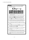
(b) Do not bundle the 24VDC power supply wires with, or run them close to, the
main circuit (high voltage, large current) and I/O signal lines (including
common line).
Reserve a distance of at least 100mm (3.94inch) from adjacent wires.
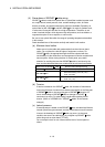
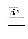
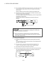
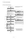
(c) Momentary power failure may be detected or the Motion controller may be
reset due to surge caused by lightening.
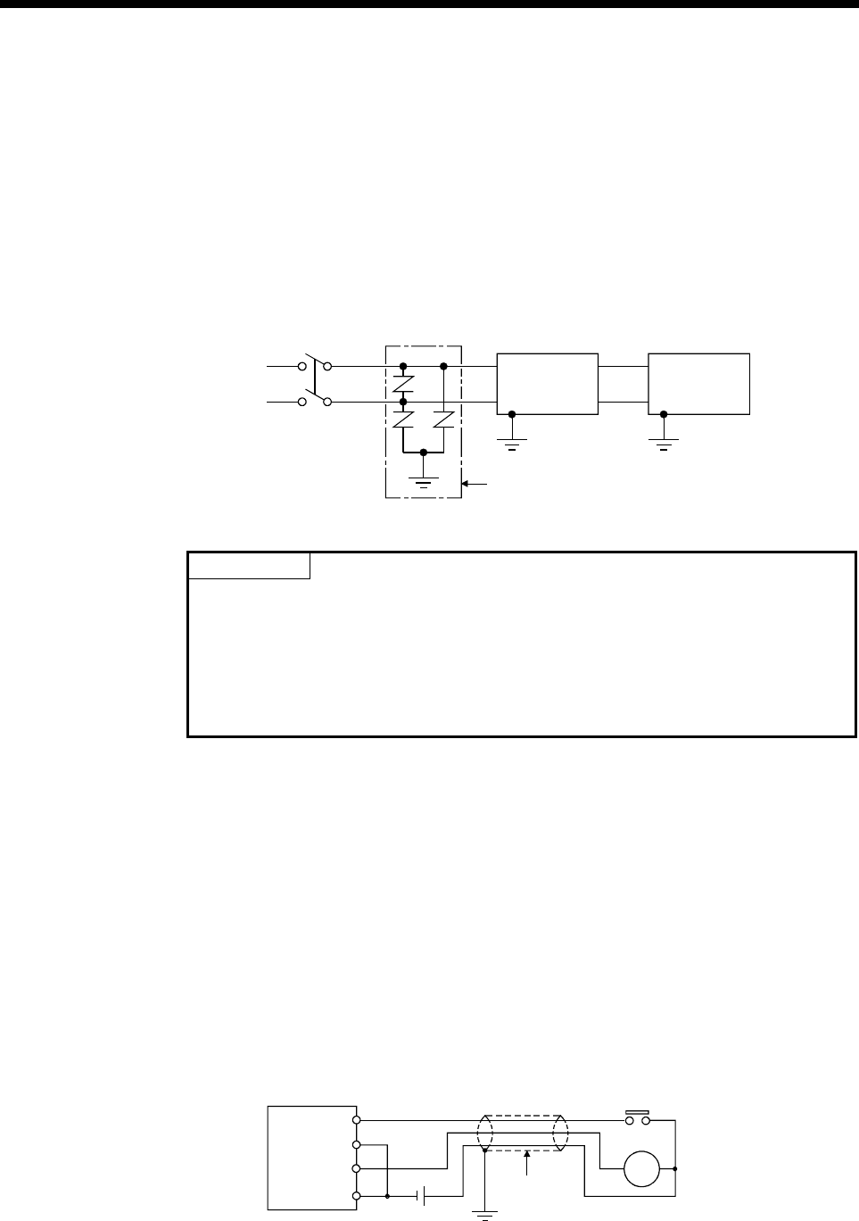
As measures against surge caused by lightening, connect a surge absorber
for lightening as shown below.
Using the surge absorber for lightening can reduce the influence of
lightening.
AC
E3
E2
24VDC
power supply
Surge absorber for lightening
E1
Motion
controller
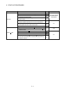
POINTS
(1) Separate the ground of the surge absorber for lighting (E1), 24VDC power
supply (E2) and Motion controller (E3).
(2) Select a surge absorber for lighting whose power supply voltage does no
exceed the maximum allowable circuit voltage even at the time of maximum
power supply voltage elevation.
(2) Wiring of I/O equipment
(a) Insulation-sleeved crimping terminals cannot be used with the terminal
block.
It is recommended to cover the wire connections of the crimping terminals
with mark or insulation tubes.
(b) The wires used for connection to the terminal block should be 0.3 to
0.75mm
2
in core and 2.8mm (0.11inch) or less in outside diameter.
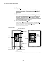
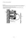
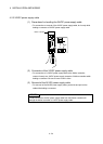
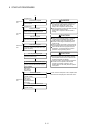
(c) Run the input and output lines away from each other.
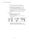
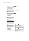
(d) When the wiring cannot be run away from the main circuit and power lines,
use a batch-shielded cable and ground it on the Motion controller side.
In some cases, ground it in the opposite side.
Input
Output
Motion controller
Shield cable
Shield
DC
RA