


APP - 25
A
PPENDICES
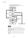
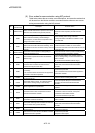
APPENDIX 1.8 Differences of I/O signals
Table 1.8 Differences of I/O signals
Item Q170MCPU Q173DCPU/Q172DCPU
I/O signal
• Q170MCPU's internal I/F
(Note-1)
• PLC I/O module
• PLC I/O module
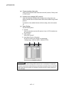
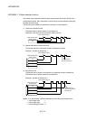
(Note-1): Real input device (PX) or real output device (PY) is in units of 16 points.
• Real input (PX): 4 points + Dummy (Unsable: Fixed at 0) 12 points
• Real output (PY): 2 points + Dummy (Unsable: Fixed at 0) 14 points
(Example) When the first I/O No. is set to 0(H).
• PX0 to PX3 (Real input), PX4 to PXF (Unsable: Fixed at 0)
• PY0 to PY1 (Real output), PY2 to PYF (Unsable: Fixed at 0)
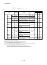
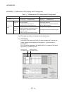
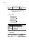
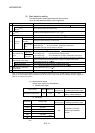
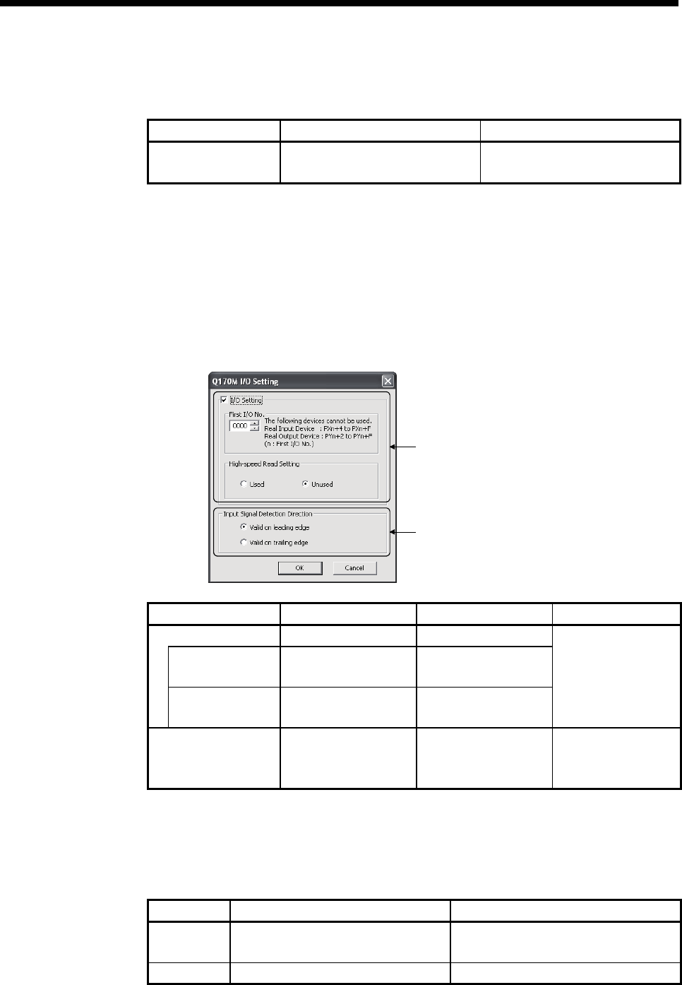
(1) Q170M I/O setting
The setting method for the I/O signals of internal I/F is shown below.
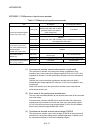
Setting for the I/O signals
Setting for the mark detection signal (DI)
Item Setting range Initial value Remarks
I/O setting Used/Unused Used
First I/O No.
0 to FF0
(in units of 16 points)
0
High-speed read
setting
Used/Unused Unused
Number of I/O points
must be total of 256
points or less.
Input signal detection
direction
Valid on leading edge/
Valid on trailing edge
Valid on leading edge
Set the detection
direction of the mark
detection signal (DI).
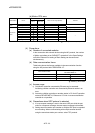
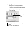
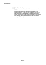
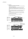
(2) Application of input signal
There are two kinds of applications of the input and mark detection for the
Q170MCPU's internal I/F.
The same signal can be used simultaneously by the input and mark detection.
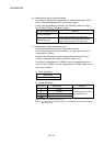
I/O setting Input signal Mark detection
Used Usable as the real input device (PX)
Usable as the real input device (PX) or
mark detection signal (DI)
Unused Unusable Usable as the mark detection signal (DI)