


2 - 47
2 SYSTEM CONFIGURATION
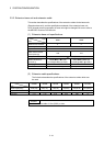
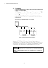
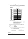
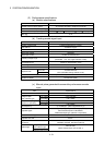
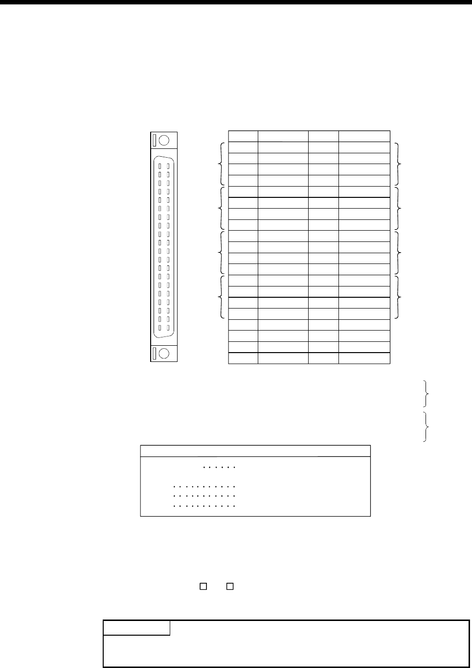
(b) The pin layout of the CTRL connector
Use the CTRL connector on the front of the Q172DLX module to connect to
servo external signals.
The following is the pin layout of the Q172DLX CTRL connector as viewed
from the front.
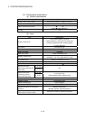
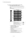
(Attachment)
RLS1
FLS1
Pin No.
B20
B19
B18
B17
Signal Name
STOP1
DOG1/CHANGE1
1
Signal No.
3
2
4
5
7
6
8
CTRL connector
For information about
signal details, refer to
the programming manual.
DOG/CHANGE Proximity dog/Speed-position
switching signal
STOP Stop signal
RLS Lower stroke limit
FLS Upper stroke limit
B16
B15
B14
B13
B12
B11
B10
B9
B8
B7
B6
B5
B4
B3
B2
B1
A20
A19
A18
A17
A16
A15
A14
A13
A12
A11
A10
A9
A8
A7
A6
A5
A4
A3
A2
A1
RLS5
FLS5
STOP5
DOG5/CHANGE5
RLS6
FLS6
STOP6
DOG6/CHANGE6
RLS7
FLS7
STOP7
DOG7/CHANGE7
RLS8
FLS8
STOP8
DOG8/CHANGE8
RLS2
FLS2
STOP2
DOG2/CHANGE2
RLS3
FLS3
STOP3
DOG3/CHANGE3
RLS4
FLS4
STOP4
DOG4/CHANGE4
COM
COM
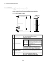
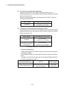
(Optional)
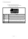
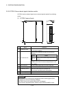
Applicable connector model name
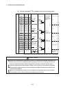
Pin No. Signal Name
Signal No.
No connect
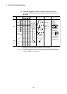
DOG/CHANGE, STOP, RLS, FLS functions of each axis(1 to 8)
No connect
No connect
No connect
No connect
No connect
A6CON2 type Crimp-contact type connector
A6CON3 type Pressure-displacement type connector
A6CON4 type soldering type connector
A6CON1 type soldering type connector
FCN-361J040-AU connector
(FUJITSU COMPONENT LIMITED)
FCN-360C040-B connector cover
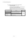
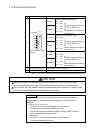
(Note) : Connector/terminal block conversion modules and cables can be
used at the wiring of CTRL connector.
A6TBXY36/A6TBXY54/A6TBX70 : Connector/terminal block
converter module
AC
TB ( :Length [m]) : Connector/terminal block
converter module cable
POINT
Signal No. 1 to 8 can be assigned to the specified axis. Make the assignment in the
system settings of MT Developer2.