


5 - 1
5 START-UP PROCEDURES
5
5. START-UP PROCEDURES
5.1 Check Items before Start-up
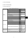
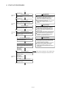
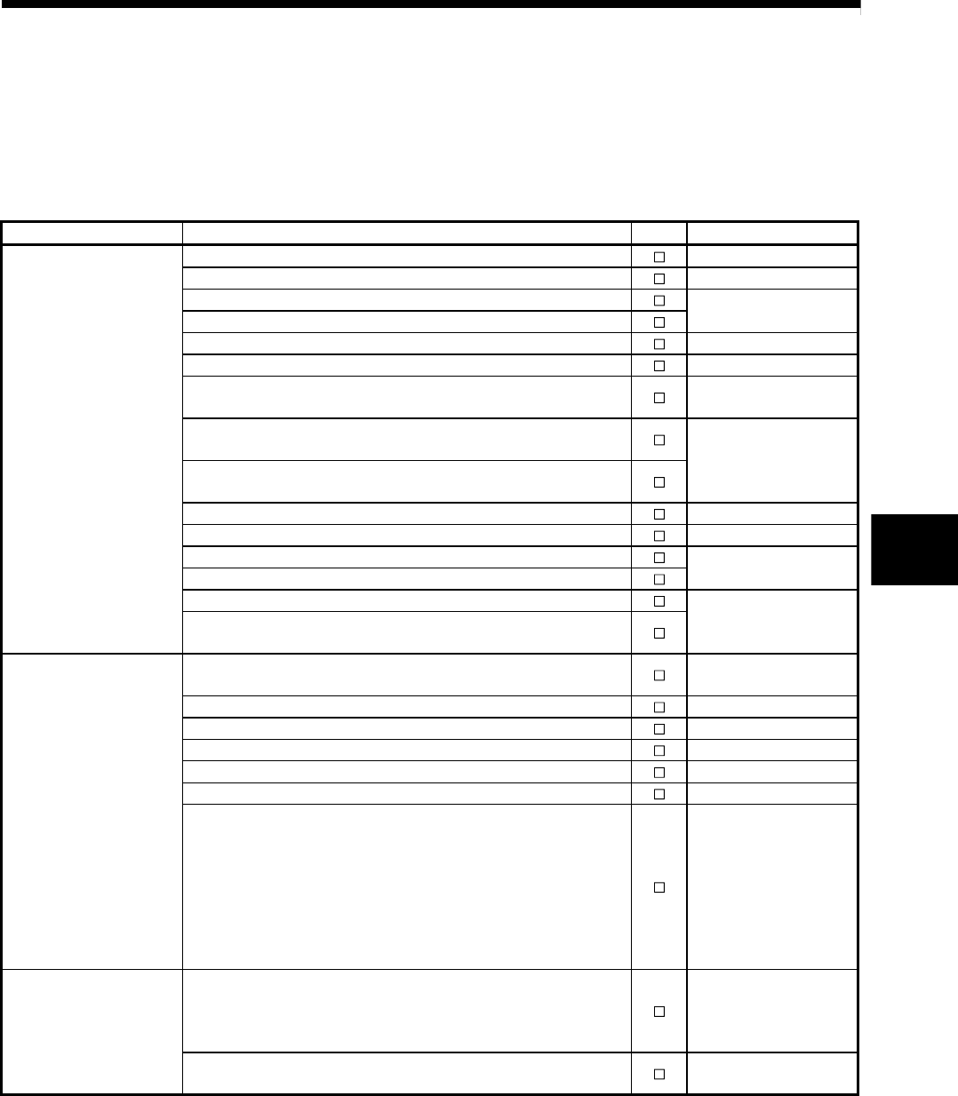
Table 5.1 Check items before start-up
Part name Confirmation Items Check Reference
(1) Check for looseness, rattling or distorted installation. 4.1.2
(2) Check that the module fixing screw tightening torque is as specified. 4.1.1
(3) Check that the wire sizes of cables are correct.
(4) Check that the power line is wired correctly.
4.3.1
(5) Check that FG is wired correctly. 4.3.2
(6) Check that the FG terminal screws are tightened correctly.
(7) Check that the FG terminal screws are tightening torque is as
specified.
4.1.1
(8) Check that the 24VDC wires are twisted as closely as possible and
run in the shortest distance.
(9) Check that the 24VDC wires are not bind the cable together with
and run close to the power wires.
4.3.1
(10) Check that grounding of the earth terminal FG. 4.3
(11) Check that the forced stop input is wired correctly. 3.2
(12) Check that the battery is installed.
(13) Check that the battery lead connecter is connected correctly.
4.1.4
(14) Check that the internal I/F is wired correctly.
Q170MCPU
Motion controller
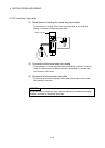
(15) Check that the manual pulse generator/incremental synchronous
encoder is wired correctly.
2.5.1
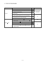
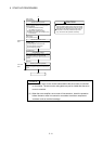
(1) Check that the extension base unit is Q52B or Q55B (type not
requiring power supply module).
2.5.2
(2) Check that the model name of module is correct. 2.3
(3) Check that the damage for installed modules.
(4) Check that the modules are installed correctly. 4.1.3
(5) Check for looseness, rattling or distorted installation. 4.1.2
(6) Check that the module fixing screw tightening torque is as specified. 4.1.1
Extension base unit
(7) Check that the total I/O points of I/O modules and intelligent function
modules do not exceed the I/O points of the Motion controller.
Refer to the "Q173DCPU/
Q172DCPU Motion
controller Programming
Manual(COMMON)", or
"QCPU User's Manual
(Hardware Design,
Maintenance and
Inspection).
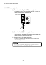
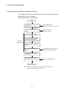
(1).Check that the installation position of modules correspond to the
system setting.
Refer to the "Q173DCPU/
Q172DCPU Motion
controller Programming
Manual(COMMON).
Q172DLX Servo external
signals interface module/
Q173DPX Manual pulse
generator interface module
(2) Check that the connection with external equipments is correct.
2.5.3
2.5.4