


1 - 5
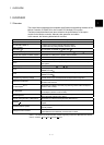
1 OVERVIEW
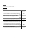
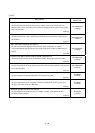
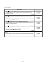
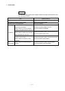
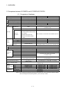
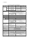
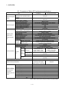
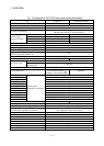
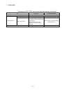
Comparison of Motion control specifications (continued)
Item Q170MCPU Q173DCPU Q172DCPU
Clock data setting Clock synchronization between Multiple CPU
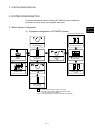
Absolute position system
Made compatible by setting battery to servo amplifier.
(Possible to select the absolute data method or incremental method for each axis)
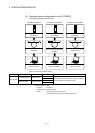
Number of SSCNET systems
(Note-3)
1 system 2 systems 1 system
PLC module which can be control
by Motion CPU (area)
Interrupt module, Input module, Output module, Input/Output composite module,
Analogue input module, Analogue output module
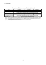
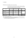
(Note-1) : When the manual pulse generator is used with the Q170MCPU's internal I/F, do not set the Q173DPX in the System Settings.
(Note-2) : Any incremental synchronous encoder connected to the Q170MCPU's internal I/F will automatically be assigned an Axis No.
one integer greater than the number of encoders connected to any Q173DPX modules.
(Note-3) : The servo amplifiers for SSCNET cannot be used.