


2 - 42
2 SYSTEM CONFIGURATION
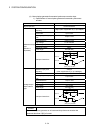
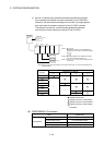
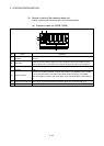
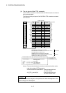
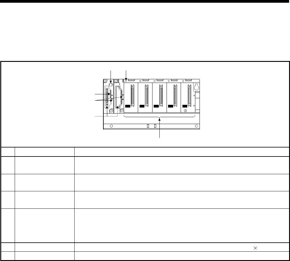
(3) Names of parts of the extension base unit
Names of parts of the extension base unit are described below.
(a) Extension base unit (Q52B, Q55B)
IN
I/O0 I/O1 I/O2 I/O3 I/O4
OUT
4)
1)
2)
3)
5)6)
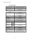
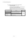
No. Name Application
1)
Extension cable
connector
Connector for connecting an extension cable (for signal communications with the extension
base unit)
2) Base cover
Protective cover of extension cable connector. Before the GOT is connected, the area
under the word "OUT" on the base cover must be removed with a tool such as nippers.
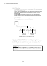
3)
Stage No. setting
connector
Connector for setting the number of stages of extension base units. (Used for setting in
stage 1.)
4) Module connector
Connector for installing the Motion modules, I/O modules, and intelligent function module.
To the connectors located in the spare space where these modules are not installed,
attach the supplied connector cover or the blank cover module (QG60) to prevent entry of
dirt.
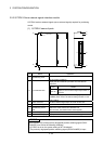
5) Module fixing screw hole Screw hole for fixing the module to the extension base unit. Screw size: M3 12
6) Base mounting hole Hole for mounting this base unit onto the panel of the control panel (for M4 screw)