


7 - 2
7 POSITIONING DEDICATED SIGNALS
7.2 Positioning Dedicated Signals
The device list of positioning dedicated signals is shown below.
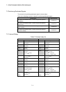
Refer to the following manuals for details of positioning dedicated signals.
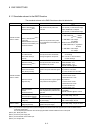
Manual Name Manual Number
Q173DCPU/Q172DCPU Motion controller Programming Manual
(COMMON)
IB-0300134
Q173DCPU/Q172DCPU Motion controller Programming Manual
(Motion SFC)
IB-0300135
Q173DCPU/Q172DCPU Motion controller Programming Manual
(REAL MODE)
IB-0300136
Q173DCPU/Q172DCPU Motion controller Programming Manual
(VIRTUAL MODE)
IB-0300137
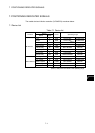
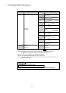
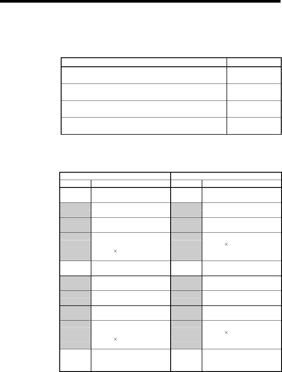
7.2.1 Internal Relays
Table 7.2 Internal relay list
SV13 SV22
Device No. Application Device No. Application
M0 M0
to
User device
(2000 points)
to
User device
(2000 points)
M2000 M2000
to
Common device
(320 points)
to
Common device
(320 points)
M2320 M2320
to
Unusable
(80 points)
to
Unusable
(80 points)
M2400 M2400
to
Axis status
(20 points 16 axes)
to
Axis status
(20 points
16 axes)
Real mode……Each axis
Virtual mode….Output module
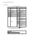
M2720 M2720
to
User device
(320 points)
(Note-1)
to
User device
(320 points)
(Note-1)
M3040 M3040
to
Unusable
(32 points)
to
Unusable
(32 points)
M3072 M3072
to
Common device (Command signal)
(64 points)
to
Common device (Command signal)
(64 points)
M3136 M3136
to
Unusable
(64 points)
to
Unusable
(64 points)
M3200 M3200
to
Axis command signal
(20 points
16 axes)
to
Axis command signal
(20 points
16 axes)
Real mode……Each axis
Virtual mode….Output module
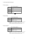
M3520 M3520
to to
M3839
User device
(320 points)
(Note-1)
M3839
User device
(320 points)
(Note-1)