


2 - 59
2 SYSTEM CONFIGURATION
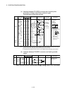
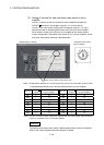
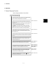
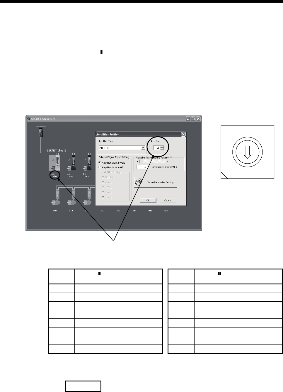
(3) Setting of the axis No. and axis select rotary switch of servo
amplifier
Axis No. is used to set the axis numbers of servo amplifiers connected to
SSCNET
connector in the program. Axis No. of 1 to 16 can be set.
Axis No. is set in the system setting of MT Developer2. Axis No. (1 to 16) is
allocated and set for the setting axis number (d01 to d16) of servo amplifier.
Since the axis number (d01 to d16) of servo amplifier on the system setting
screen corresponds to axis select rotary switch (0 to F) of servo amplifier, set the
axis select rotary switch referring to the table below.
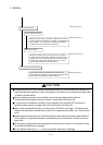
•
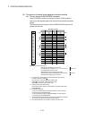
Setting display of axis No.
Set the axis No. relative to axis number (dno.).
•
Axis select rotary switch
(Servo amplifier)
1
C
B
A
9
8
7
6
5
4
3
2
0
F
E
D
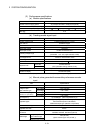
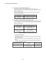
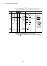
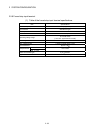
(Note) : Correspondence between dno. and axis select rotary switch of servo amplifiers is shown below.
Correspondence between dno.s and axis select switches of servo amplifier
dno.
(Note)
SSCNET
system
Axis select rotary switch
of servo amplifier
dno.
(Note)
SSCNET
system
Axis select rotary switch
of servo amplifier
d01 1 "0" d09 1 "8"
d02 1 "1" d10 1 "9"
d03 1 "2" d11 1 "A"
d04 1 "3" d12 1 "B"
d05 1 "4" d13 1 "C"
d06 1 "5" d14 1 "D"
d07 1 "6" d15 1 "E"
d08 1 "7" d16 1 "F"
(Note) : The dno. is number of servo amplifier axis displayed with the system setting of MT Developer2.
Axis No. is set relative to dno. in the system settings.
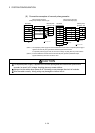
REMARK
The setting of axis select rotary switch is different depending on the servo amplifier.
Refer to the "Servo amplifier Instruction Manual" for details.