


APP - 4
A
PPENDICES
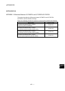
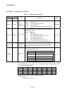
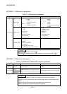
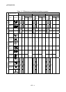
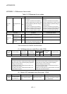
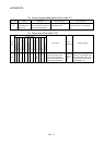
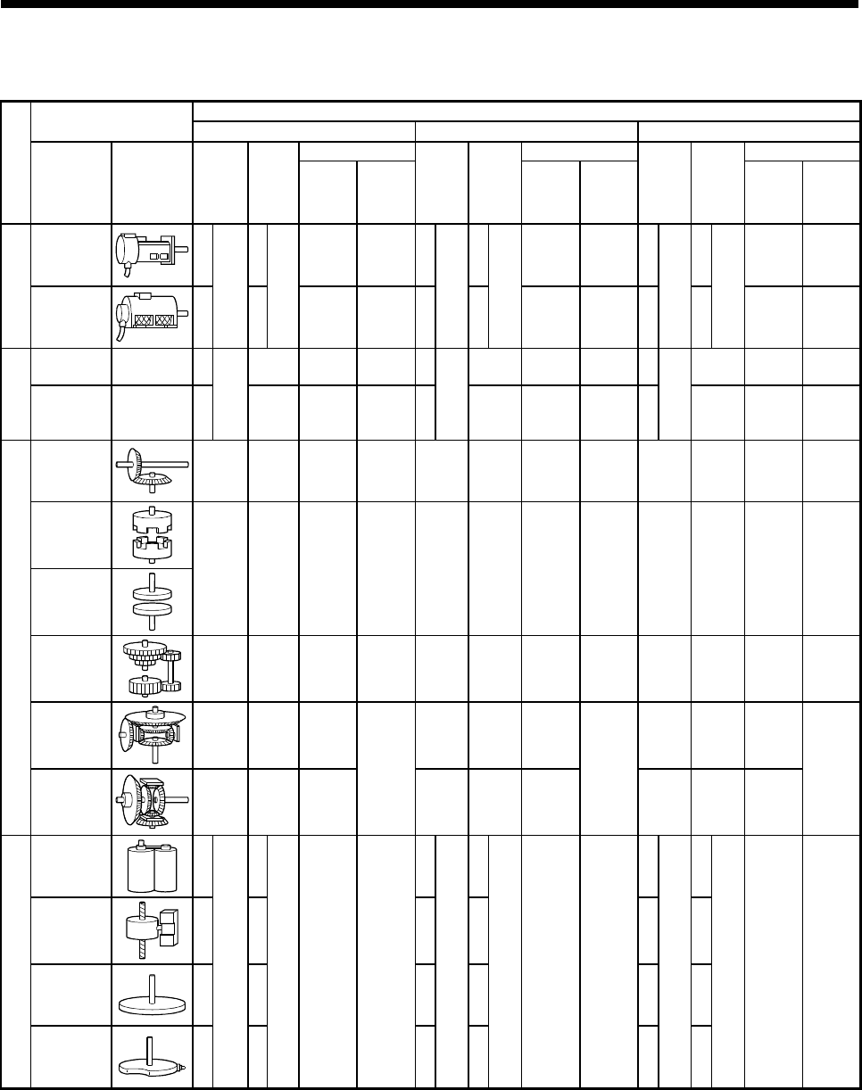
Table 1.4 Differences of mechanical system programs
Maximum number of usable
Mechanical module
Q170MCPU Q173DCPU Q172DCPU
Number per block Number per block Number per block
Classification
Name Appearance
Number
per
Motion
controller
Number
per
system
Connection
shaft side
Auxiliary
input axis
side
Number
per
Motion
CPU
module
Number
per
system
Connection
shaft side
Auxiliary
input axis
side
Number
per
Motion
CPU
module
Number
per
system
Connection
shaft side
Auxiliary
input axis
side
Virtual servo
motor
16 16 — — 32 32 — — 8 8 — —
Drive module
Synchronous
encoder
8
Total
24
8
Total
18
— — 12
Total
44
12
Total
34
— — 8
Total
16
8
Total
10
— —
Virtual main
shaft
— 16 16 — — 32 32 — — 8 8 — —
Virtual axis
Virtual
auxiliary input
axis
— 16
Total
32
16 — — 32
Total
64
32 — — 8
Total
16
8 — —
Gear
32 32 1 1 64 64 1 1 16 16 1 1
Direct clutch
Smoothing
clutch
32 32 1 1 64 64 1 1 16 16 1 1
Speed
change gear
32 32 1 1 64 64 1 1 16 16 1 1
Differential
gear
16 16 1 32 32 1 8 8 1
Transmission module
Differential
gear to main
shaft
16 1 –-
–-
32 1 —
—
8 1 —
—
Roller
16 16 32 32 8 8
Ball screw
16 16 32 32 8 8
Rotary table
16 16 32 32 8 8
Output module
Cam
16
Total
16
16
Total
16
1 1
32
Total
32
32
Total
32
1 1
8
Total
8
8
Total
8
1 1