


2 - 26
2 SYSTEM CONFIGURATION
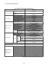
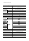
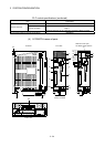
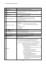
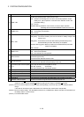
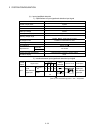
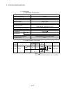
No. Name Application
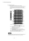
13) "ERR." LED
Indicates the operating status of the PLC CPU area.
• ON : Detection of self-diagnosis error which will not stop operation, except
battery error. (When operation continued at error detection is set in the
parameter setting.)
• OFF : Normal
• Remains flashing :Detection of error whose occurrence stops operation.
Resetting with the RUN/STOP/RESET switch becomes valid.
14) "USER" LED
Indicates the operating status of the PLC CPU area.
• ON : Annunciator (F) turned ON
• OFF : Normal
15) "BAT." LED
Indicates the operating status of the PLC CPU area.
• ON (yellow) : Occurrence of battery error due to reduction in battery voltage of the
memory card.
• ON (green) : Turned ON for 5 seconds after restoring of data backup to the
standard ROM by the latch data backup is completed.
• Remains flashing (green): Backup of data to the standard ROM by latch data
backup is completed.
• OFF : Normal
16) "BOOT" LED
Indicates the operating status of the PLC CPU area.
• ON : Start of boot operation
• OFF : Non-execution of boot operation
17) USB connector
• Connector to connect the peripheral devices for USB connection
(Connector type mini B)
• Connect with the dedicated cable for USB
18) RS-232 connector
• Connector to connect the peripheral devices for RS-232 connection
• Connect with the dedicated cable (QC30R2) for RS-232
19)
Forced stop input connector (EMI)
(Note-2)
Input to stop all axes of servo amplifier in a lump
EMI ON (opened) : Forced stop
EMI OFF (24VDC input) : Forced stop release
20) Memory card EJECT button Used to eject the memory card from the Motion controller
21) Memory card loading connector Connector used to load the memory card to the Motion controller
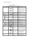
22) Battery holder
(Note-3)
Battery holder to set the Q6BAT/Q7BAT
23) Module fixing screw hole
(Note-4)
Hole for screw used to fix to the control panel
24) FG terminal Ground terminal connected with the shield pattern of the printed circuit board
25) Extension cable connector Connector for transfer of signals to/from the extension base unit.
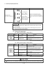
(Note-1) : Put the SSCNET cable in the duct or fix the cable at the closest part to the Motion controller with bundle
material in order to prevent SSCNET
cable from putting its own weight on SSCNET connector.
(Note-2) : Be sure to use the cable for forced stop input (sold separately). The forced stop cannot be released without
using it.
If the cable for forced stop input is fabricated on the customer side, make it within 30m(98.43ft.).
(Note-3) : Be sure to set the battery. The data (Refer to Section 6.5.) of RAM built-in Motion controller are not backed up if
the battery cable is not set correctly.
(Note-4) : Purchase the M5 screws.