


APP - 35
A
PPENDICES
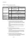
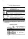
(e) Mark detection data storage device
Set the mark detection data storage device (first device to use in the
"Specified Number of Detections mode" or "Ring Buffer mode").
When using the "Specified Number of Detections mode" or "Ring Buffer
mode", reserve the device area to accommodate the number of detections.
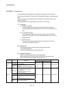
Word device
Setting range
(Note-1)
Remarks
D 0 to 8191
W 0 to 1FFF
#
0 to 9215
(Note-2)
U \G
10000 to (10000+p-1)
(Note-3)
—
(Note-1): Set an even numbered device in the 32-bit integer type/64-bit floating-point type.
(Note-2): The data can be stored in #9216 to #12287 in the "Specified Number of Detections mode"
or "Ring Buffer mode".
(Note-3): "p" indicates the user setting area points of the Multiple CPU high speed transmission area
for each CPU.
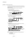
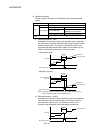
(f) Mark detection data range
When the data at mark detection is within the range, they are stored in the
mark detection data storage device and the number of mark detections
counter is incremented by 1.
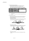
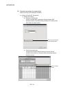
• Upper value > Lower value
The mark detection is executed when the mark detection data is "greater or
equal to the lower value and less than or equal to the upper value".
Upper value
Lower value
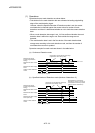
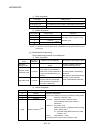
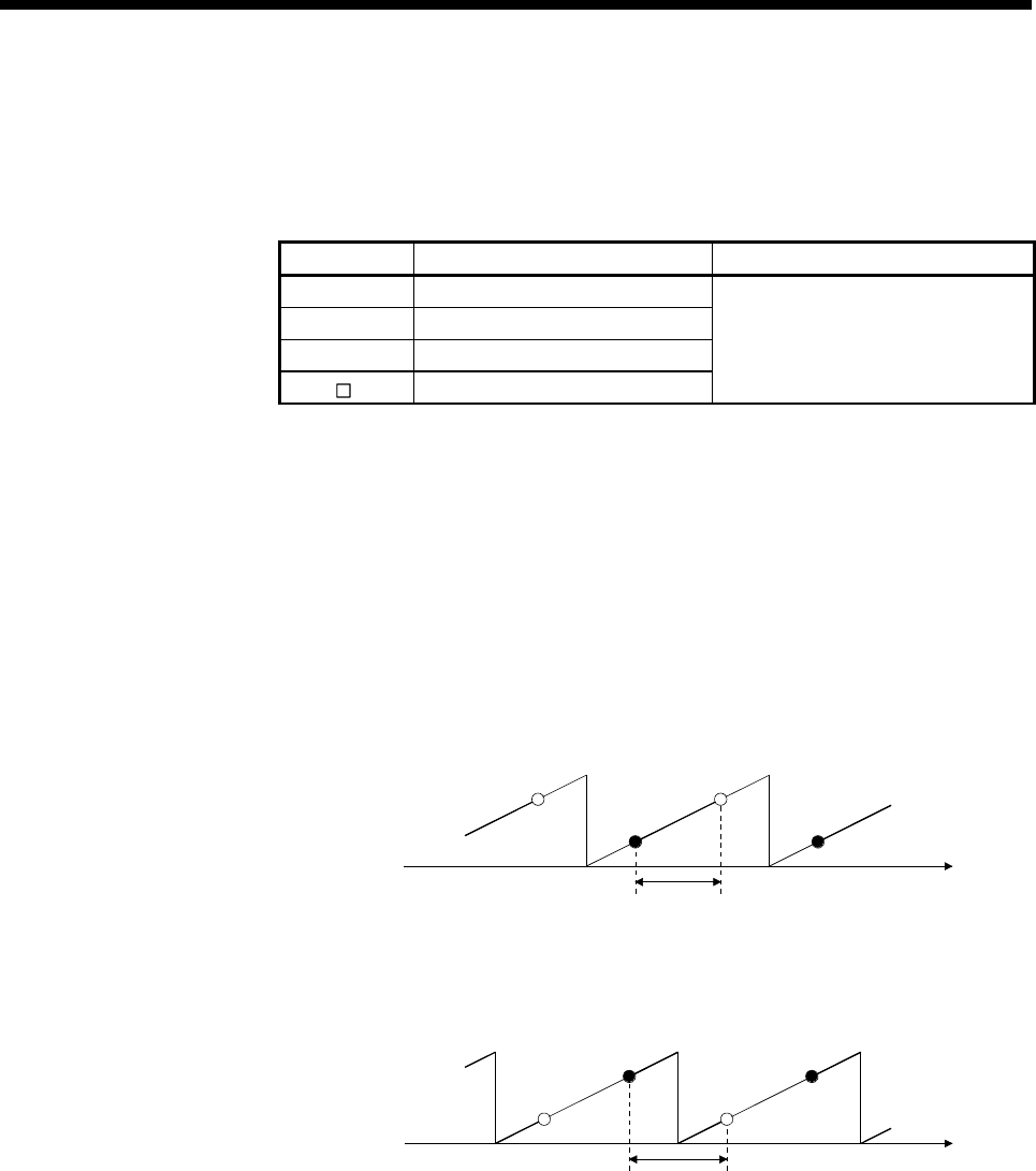
• Upper value < Lower value
The mark detection is executed when the mark detection data is " greater
or equal to the lower value or less than or equal to the upper value".
Upper limit
value
Lower limit
value
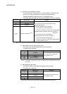
• Upper value = Lower value
The mark detection range is not checked. The mark detection is always
executed.