


2 - 38
2 SYSTEM CONFIGURATION
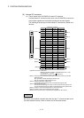
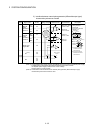
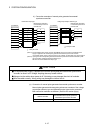
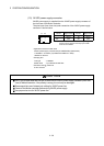
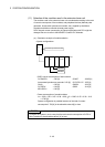
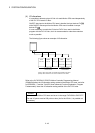
(f) Axis No. of manual pulse generator/incremental synchronous encoder
Any incremental synchronous encoder connected to the Q170MCPU's
internal I/F will automatically be assigned an axis No. one integer greater
than the number of encoders connected to any Q173DPX modules.
The setting for the axis No. of manual pulse generator/incremental
synchronous encoder used by the internal I/F and Q173DPX.
P7 to P8
P4 to P6
P1 to P3
(Note-3)
(Note-2)
(Note-3)
P
(Note-1)
Q170M
CPU
Q173D
PX
Q173D
PX
Q173D
PX
Internal I/F
(Note-1): = Axis No.
The following Axis No.s are automatically set
depending on the number of Q173DPX modules.
0: P1
1: P4
2: P7
(Note-2): Q173DPX installed to the smallest slot number
of the extension base unit is the 1st.
(Note-3): Axis No. P1 to P3 of the ma nual pulse generator
can be used.
(Note): When the manual pulse generator is used with the internal I/F, do not set the Q173DPX in the
System Settings.
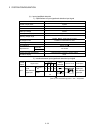
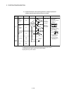
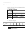
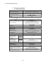
1st 2nd 3rd
Number of Q173DPXs
Axis No.
0 1 2 3
P1
P2
P3
1
1
1
P4
P5
P6
2
2
P7
P8
—
—
—
3
: Usable by internal I/F.
1
: Usable only by the 1st Q173DPX
2
: Usable only by the 2nd Q173DPX
3
: Usable only by the 3rd Q173DPX
—: Unusable
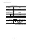
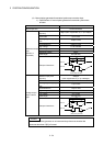
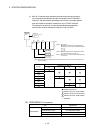
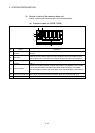
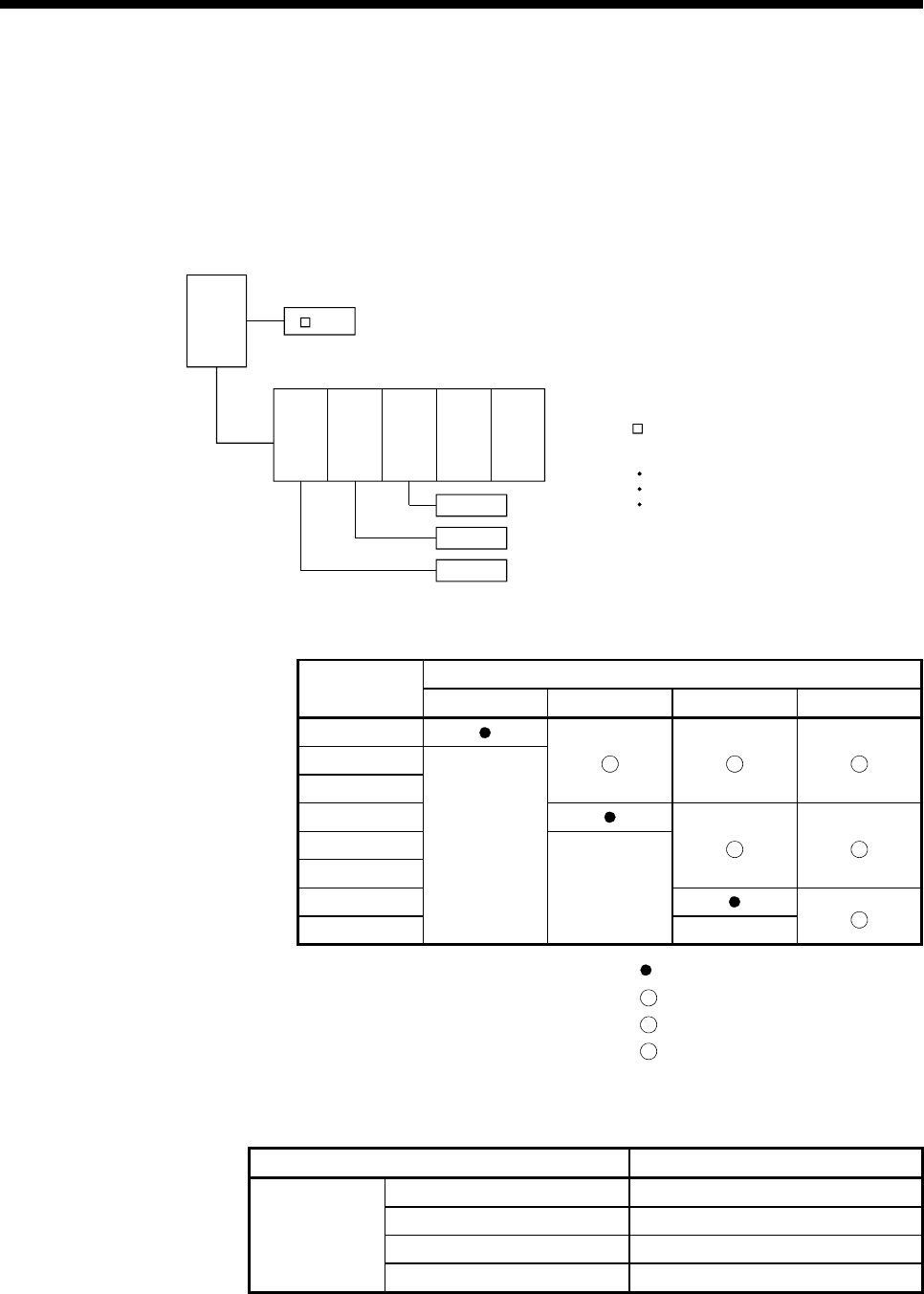
(9) PERIPHERAL I/F connector
Item Specification
Data transmission speed 100Mbps/10Mbps
Communication mode Full-duplex/Half-duplex
Transmission method Base band
Transmission
Cable length [m(ft.)] Up to 30 (98.43)