


2 - 43
2 SYSTEM CONFIGURATION
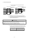
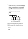
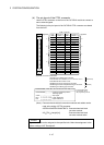
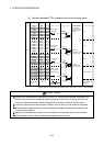
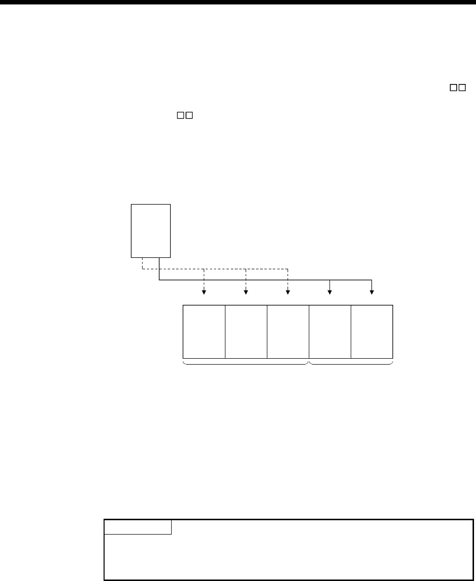
(4) I/O allocations
It is possible to allocate unique I/O No.s for each Motion CPU area independently
of the PLC CPU area’s I/O No.s.
ON/OFF data input to the Motion CPU area is handled via input devices PX
,
while ON/OFF data output from the Motion CPU area is handled via output
devices PY
.
It is not mandatory to match the I/O device PX/PY No.s used in the Motion
program with the PLC I/O No.s; but it is recommended to make them match as
much as possible.
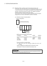
The following figure shows an example of I/O allocation.
0
Q170MCPU
312 4
QY41
PY20 to PY3F
(Y60 to Y7F)
QX41
X0 to X1F
Q62DA
20 to 3F
QX41
PX0 to PX1F
(X40 to X5F)
PLC CPU area
control module
Motion CPU area
control module
QY41
Y80 to Y9F
(Note-1): When the number of modules to be installed is 32 points.
(Note-2): When the PX/PY No. does not match the PLC I/O No.
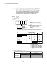
Refer to the Q173DCPU/Q172DCPU Motion Controller Programming Manual
(COMMON) about the I/O allocation setting method of the Motion CPU area, and refer
to APPENDIX 1.7 and the "QnUCPU User's Manual (Function Explanation, Program
Fundamentals)" about the I/O allocation setting method of the PLC CPU area.
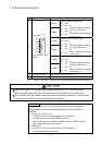
POINT
I/O device of the Motion CPU area can be set in the range PX/PY000 to PX/PYFFF.
The real I/O points must be 256 points or less. (As for the I/O No., it is possible not
to continue.)