


2 - 49
2 SYSTEM CONFIGURATION
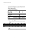
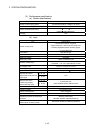
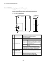
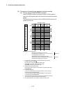
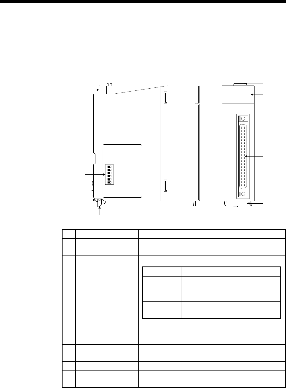
2.5.4 Q173DPX Manual pulse generator interface module
Q173DPX receive signals required for Manual pulse and Incremental synchronous
encoder (Voltage-output/Open-collector type/Differential-output type) input.
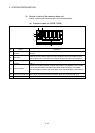
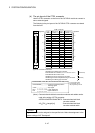
(1) Q173DPX name of parts
61 2345
ON
Q173DPX
Q173DPX
1
2
3
PLS.A
1
2
3
PLS.B
1
2
3
TREN
PULSER
7)
5)
6)
2)
1)
3)
8)
4)
No.
Name Application
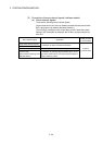
1) Module fixing hook
Hook used to fix the module to the base unit.
(Single-motion installation)
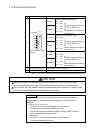
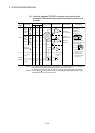
Display the input status from the external equipment.
LED Details
PLS.A 1 to 3
PLS.B 1 to 3
Display for input signal status of manual
pulse generator/incremental synchronous
encoder phases A, B
TREN 1 to 3
Display for signal status of tracking
enable.
2) Input indicator LED
The manual pulse generator/incremental synchronous
encoder phases A, B and tracking enable signal does not
turn ON without setting Q173DPX in the system setting.
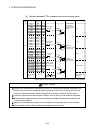
3) PULSER connector
Input connector of the Manual pulse generator/Incremental
synchronous encoder.
4) Module mounting lever Used to install the module to the base unit.
5) Module fixing screw hole
Hole for the screw used to fix to the base unit
(M3×12 screw : Purchase from the other supplier)