


6 - 4
6 INSPECTION AND MAINTENANCE
6.2 Daily Inspection
The items that must be inspected daily are shown below.
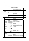
Table 6.1 Daily Inspection
Item Inspection item Inspection Criterion Action
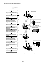
1
Mounting of Motion
controller
2 Mounting of base unit
Check that the fixing
screws are not loose and
the cover is not dislocated.
The screws and cover must be mounted securely.
Retighten the
screws.
3
Installation of Motion
modules and I/O
modules
Check that the module is
not dislocated and the unit
fixing hook is engaged
securely.
The module fixing hook must be engaged and installed
correctly.
Securely
engaged the
module fixing
hook.
Check for loose terminal
screws.
Screws should not be loose.
Retighten the
terminal screws.
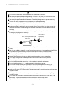
Check for distance between
solderless terminals.
The proper clearance should be provided between solderless
terminals.
Correct.
4 Connecting conditions
Check the connector part of
the cable.
Connections should not be loose.
Retighten the
connector fixing
screws.
[POWER] LED Check that the LED is ON.
The LED must be ON.
(Abnormal if the LED is OFF.).
[MODE] LED Check that the LED is ON.
The LED must be ON.
(Abnormal if the LED is OFF or flickering.)
[RUN] LED
Check that the LED is ON
in RUN status.
The LED must be ON.
(Abnormal if the LED is OFF.)
[ERR.] LED Check that the LED is OFF.
The LED must be OFF.
(Abnormal if the LED is ON or flickering.)
[BAT.] LED Check that the LED is OFF.
The LED must be OFF.
(Abnormal if the LED is ON (yellow).)
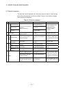
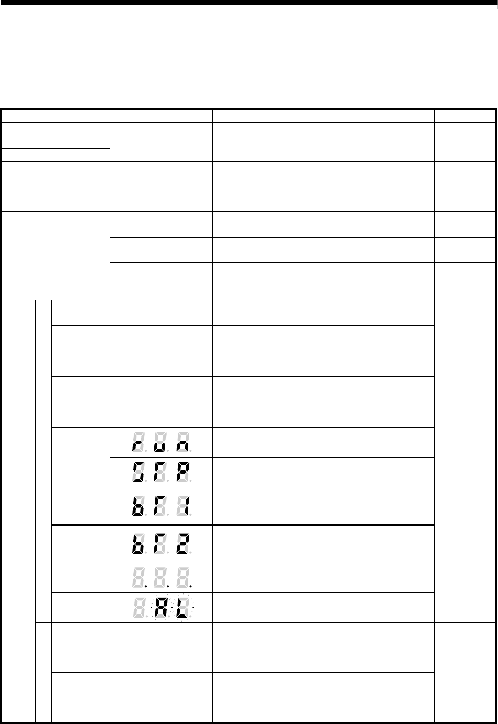
Steady "RUN" display.
(Abnormal if "RUN" does not display or incorrect display.)
Normal
Steady "STP" display.
(Abnormal if "STP" does not display or incorrect display.)
Refer to Section
2.5.1
Battery error
warning
(2.7V or less)
"BT1" does not display.
(Abnormal if steady "BT1" display.)
Battery error
warning
(2.5V or less)
"BT2" does not display.
(Abnormal if steady "BT2" display.)
Refer to Section
6.5
WDT error
" . . . " does not display.
(Abnormal if steady " . . ." display.)
Motion controller
Others
" AL" does not flash.
(Abnormal if " . . ." flashes.)
Refer to Section
2.5.1
Input LED
Check that the LED is
ON/OFF.
The LED must be ON when the input power is turned ON.
The LED must be OFF when the input power is turned OFF.
(Abnormal if the LED does not turn ON or turn OFF as
indicated above.)
5
Module indication LED
I/O module
Output LED
Check that the LED is
ON/OFF.
The LED must be ON when the output power is turned ON.
The LED must be OFF when the output power is turned OFF.
(Abnormal if the LED does not turn ON or turn OFF as
indicated above.)
Refer to
"I/O Module
Type Building
Block User's
Manual".