


4 - 4
4 INSTALLATION AND WIRING
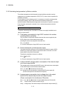
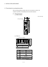
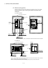
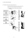
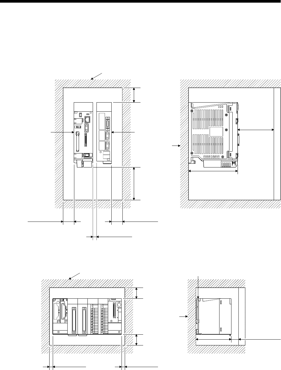
(2) Module mounting position
Keep the clearances shown below between the top/bottom faces of the module
and other structures or parts to ensure good ventilation and facilitate module
replacement.
(a) Motion controller
Top of panel or wiring duct
Motion
controller
(Note-1)
30mm(1.18inch)
or more
10mm(0.39inch)
or more
90mm(3.54inch)
or more
Door
Panel
Servo amplifier
100mm
(3.94inch)
or more
40mm(1.58inch)
or more
135mm(5.31inch)
30mm(1.18inch)
or more
(Note-1) : Fit the Motion controller at the left side of the servo amplifier.
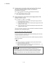
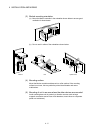
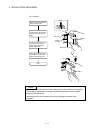
(b) Base unit
5mm(0.20inch)
or more
(Note-1)
IN OUT
Top of panel or wiring duct
5mm(0.20inch)
or more
30mm(1.18inch)
or more
30mm(1.18inch)
or more
(Note-3)
Base unit
Door
Panel
98mm(3.86inch)
20mm(0.79inch)
or more
(Note-2)
(Note-1) : 20mm(0.79inch) or more when the adjacent module is not removed and the extension cable is connected.
(Note-2) : 80mm(3.15inch) or more for the connector type.
(Note-3) : For wiring duct with 50mm(1.97inch) or less height. 40mm(1.57inch) or more for other cases.