


2 - 36
2 SYSTEM CONFIGURATION
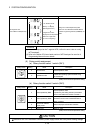
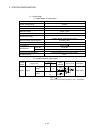
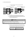
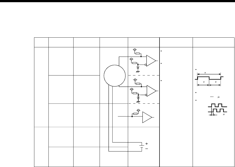
3) Interface between manual pulse generator (voltage-output/open-
collector type)/incremental synchronous encoder
A
Manual pulse
generator/
Incremental
synchronous
encoder
5V
SG
No connect
B
Power supply
5VDC
2.5 s
or more
Input or
Output
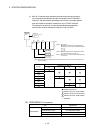
Signal name Pin No. Wiring example Internal circuit Specification Description
Input
Power
supply
SG
Rated input voltage
5.5VDC or less
HIGH level
3 to 5.25VDC/
2mA or less
For connection manual
pulse generator/
incremental
synchronous encoder
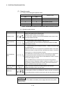
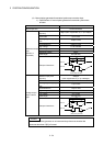
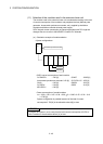
Phases A, B
(1) Positioning address
increases if Phase A
leads Phase B.
Phase A
2.5 s or
Phase B
more
(Duty ratio: 50%)
LOW level
1VDC or less/
5mA or more
5 s or more
Leading edge, Trailing
edge time 1.2 s or less
Phase difference
(2) Positioning address
decreases if Phase B
leads Phase A.
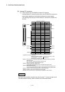
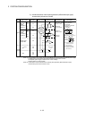
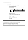
P5
(Note-1)
20
21
49
45
46
47
48
50
Pulse width
2.5 s
or more
Manual
pulse
generator,
phase A
HA
Manual
pulse
generator,
phase B
HB
Select type
signal
SEL
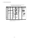
(Note-1): The 5V(P5)DC power supply from the Q170MCPU must not be used if a separate power supply
is applied to the manual pulse generator/incremental synchronous encoder.
If a separate power supply is used, be sure it is 5V voltage.
Anything else may cause a failure.