


APP - 57
A
PPENDICES
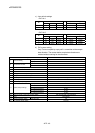
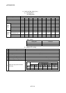
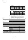
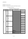
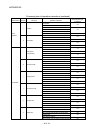
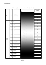
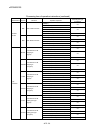
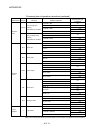
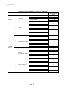
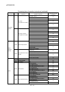
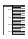
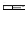
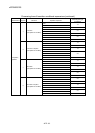
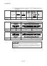
Processing time of operation instructions (continued)
Classifications Symbol Instruction Operation expression
Processing time [µs]
Q170MCPU
SET M1000 = M0 2.5
SET M1000 = X100 3.5
7.5
SET M1000 = PX0
4.5
(Note)
(None)
ON (normally open
contact)
(Completion of condition)
SET M1000 = U3E1\G10000.0 3.5
SET M1000 = !M0
SET M1000 = !X100
3.0
7.0
SET M1000 = !PX0
4.0
(Note)
Bit device
status
!
OFF (normally closed
contact)
(Completion of condition)
SET M1000 = !U3E1\G10000.0 3.5
SET M1000 2.0
SET Y100 2.5
3.5
SET PY0
4.0
(Note)
SET Device set
SET U3E1\G11000.0 2.5
RST M1000 2.0
RST Y100 2.5
3.5
RST PY0
4.0
(Note)
RST Device reset
RST U3E1\G11000.0 3.0
DOUT M0,#0 3.0
DOUT M0,#0L
DOUT Y100,#0
2.5
DOUT Y100,#0L 4.0
4.0
DOUT PY0,#0
4.5
(Note)
5.5
DOUT Device output
DOUT PY0,#0L
5.5
(Note)
DIN #0,M0
DIN #0L,M0
3.0
DIN #0,X0 2.5
DIN #0L,X0 3.0
8.0
DIN #0,PX0
4.0
(Note)
10.5
DIN Device input
DIN #0L,PX0
4.0
(Note)
OUT M100 = M0 2.5
OUT Y0 = M0 3.0
4.0
OUT PY0 = M0
4.0
(Note)
Bit device
control
OUT Bit device output
OUT U3E1\G10000.0 = M0 3.5
SET M1000 = M0*M1 3.0
SET M1000 = X100*X101 4.0
10.0
SET M1000 = PX0*PX1
4.5
(Note)
Logical
operation
* Logical AND
SET M1000 = U3E1\G10000.0*U3E1\G10000.1 3.5
(Note): The processing time that the I/O modules (PX/PY) are used with the Q170MCPU's internal I/F (DI/DO).