


2 - 25
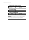
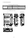
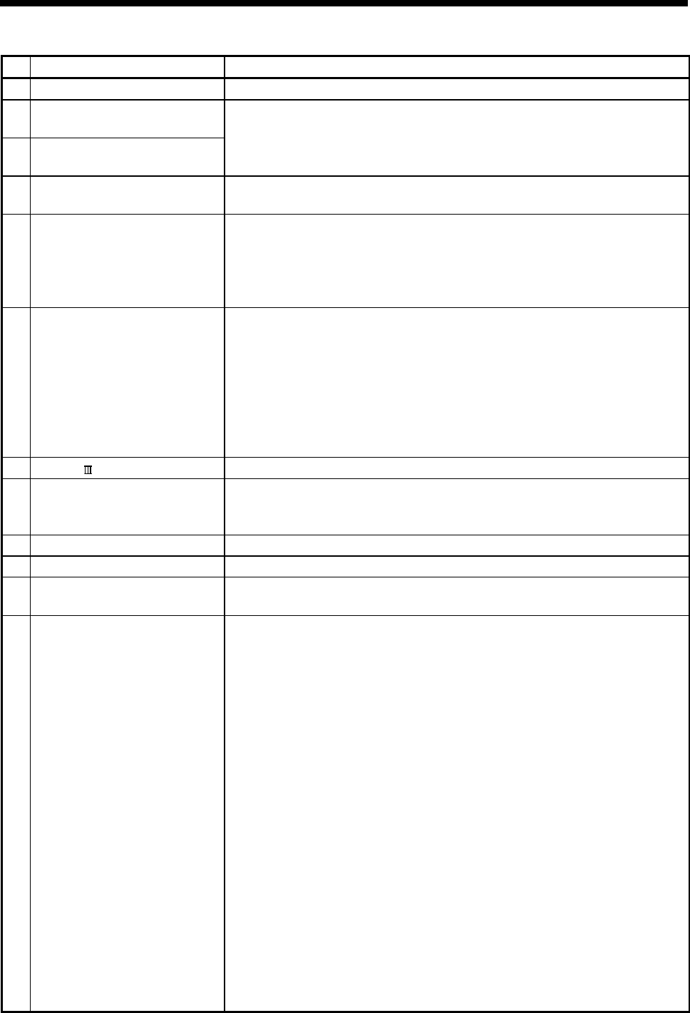
2 SYSTEM CONFIGURATION
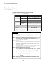
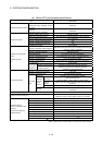
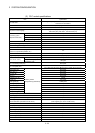
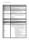
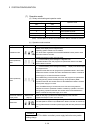
No. Name Application
1) 7-segment LED Indicates the operating status and error information.
2)
Rotary function select 1 switch
(SW1)
3)
Rotary function select 2 switch
(SW2)
• Set the operation mode.
(Normal operation mode, Installation mode, Mode operated by ROM, etc)
• Each switch setting is 0 to F.
(Factory default in SW1 "A", SW2 "0" position)
4)
"POWER" LED
• ON (red) : The internal power (5VDC) is ON.
• OFF : The internal power (5VDC) is OFF.
5)
RUN/STOP/RESET switch
• Move to RUN/STOP
RUN : Sequence program/Motion SFC program is started.
STOP : Sequence program/Motion SFC program is stopped.
• RESET (Momentary switch)
Set the switch to the "RESET" position 1 second or more to reset the hardware.
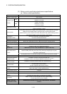
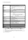
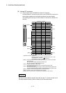
6)
PERIPHERAL I/F connector
For communication I/F with peripheral devices
• Upper LED
Remains flashing : It communicates with the personal computer.
ON : It does not communicate with the personal computer.
• Lower LED
Data transmission speed
ON : 100Mbps
OFF : 10Mbps
7)
SSCNET
CN1 connector
(Note-1)
Connector to connect the servo amplifier
8)
Internal I/F connector
Connector to connect the manual pulse generator/incremental synchronous
encoder, or to input/output the signals.
(Voltage-output/open-collector type, Differential-output type)
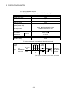
9)
24VDC power supply connector The DC power of 24VDC is connected.
10)
Serial number display Displays the serial number described on the rating plate.
11)
"MODE" LED
Indicates the mode of the PLC CPU area.
• ON (green) : Q mode
12)
"RUN" LED
Indicates the operating status of the PLC CPU area.
• ON : During operation with the RUN/STOP/RESET switch set to "RUN".
• OFF : During stop with the RUN/STOP/RESET switch set to "STOP".
When an error is detected and operation must be halted due to the error.
• Remains flashing : Parameters or programs are written with the RUN/STOP/
RESET switch set to "STOP", and then the RUN/STOP/
RESET switch is turned from "STOP" to "RUN".
• To turn ON the "RUN" LED after writing the program, carry
out the following steps.
1) Set the RUN/STOP/RESET switch in the order of "RUN"
to "STOP" to "RUN".
2) Reset with the RUN/STOP/RESET switch.
3) Power ON the Motion controller again.
• To turn ON the "RUN" LED after writing the parameters,
carry out the following steps.
1) Reset with the RUN/STOP/RESET switch.
2) Power ON the Motion controller again.
(If the RUN/STOP/RESET is set in the order of "RUN" to
"STOP" to "RUN" after changing the parameters, network
parameters and intelligent function module parameters
will not be updated.