


2 - 5
2 SYSTEM CONFIGURATION
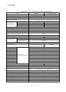
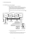
2.1.3 Function explanation of the Q170MCPU Motion controller
(1) Whole
(a) The Multiple CPU high speed bus is equipped with between the PLC CPU
area and Motion CPU area. With this reserved Multiple CPU high speed bus,
data transfer of 0.88ms period is possible for up to 14k words.
(b) Data transfer between the PLC CPU area and Motion CPU area is possible
by Multiple CPU high speed transmission memory or automatic refresh.
(c) The Multiple CPU high speed transmission cycle is synchronized with the
motion control cycle thus optimizing the control system.
(2) PLC CPU area
(a) The I/O modules, analog I/O modules, pulse I/O modules, positioning
modules, information modules and network can be controlled with the
sequence program.
(b) The device data access and program start of the Motion CPU area can be
executed by the Motion dedicated PLC instructions.
(c) The real-time processing can be realized by the Multiple CPU synchronous
interrupt program.
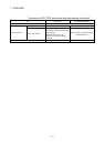
(3) Motion CPU area
(a) Up to 16 axes servo amplifiers per 1 system can be controlled in
Q170MCPU.
(b) It is possible to set the program which synchronized with the motion
operation cycle and executed at fixed cycle (0.44[ms], 0.88[ms], 1.77[ms],
3.55[ms], 7.11[ms], 14.2[ms]).
(c) It is possible to execute a download of servo parameters to servo amplifier,
servo ON/OFF to servo amplifier and position commands, etc. by connecting
between the Q170MCPU and servo amplifier with SSCNET
cable.
(d) It is possible to select the servo control functions/programming languages by
installing the corresponding operating system software in the Q170MCPU.
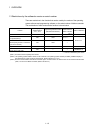
(e) Motion modules (Q172DLX/Q173DPX) are controlled with the Motion CPU
area, and the signals such as stroke limit signals connected to Motion
modules and incremental synchronous encoder can be used as motion
control.
(f) The synchronous control can be executed by using the incremental
synchronous encoder (up to 8 axes). The incremental synchronous encoder
(1 axis) built-in Q170MCPU can also be used.
(g) The stroke limit signals and proximity dog signals connected to the servo
amplifiers can be used for the motion control.
(h) I/O controls (DI 4 points, DO 2 points) built-in Q170MCPU (Motion CPU
area) can be realized.