


3 - 9
3 DESIGN
3.2.2 Safety circuit design
(1) Concept of safety circuits
When the Motion controller is powered on and off, normal control output may not
be done momentarily due to a delay or a startup time difference between the
Motion controller power supply and the external power supply (DC in particular)
for the control target.
Also, an abnormal operation may be performed if an external power supply fault
or Motion controller failure takes place.
To prevent any of these abnormal operations from leading to the abnormal
operation of the whole system and in a fail-safe viewpoint, areas which can result
in machine breakdown and accidents due to abnormal operations
(e.g. emergency stop, protective and interlock circuits) should be constructed
outside the Motion controller.
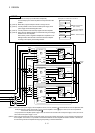
(2) Emergency stop circuit
The circuit should be constructed outside of the Motion controller or servo
amplifier. Shut off the power supply to the external servo amplifier by this circuit,
make the electromagnetic brakes of the servomotor operated.
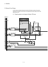
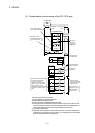
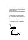
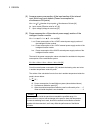
(3) Forced stop circuit
(a) The forced stop of all servo amplifiers is possible in a lump by using the
forced stop input of Motion controller. After forced stop, the forced stop
factor is removed and the forced stop canceled.
(The servo error detection signal does not turn on with the forced stop.)
The forced stop input cannot be invalidated in the parameter setting of
system setting.
Make the forced stop input cable within 30[m](98.43[ft.]).
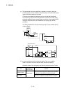
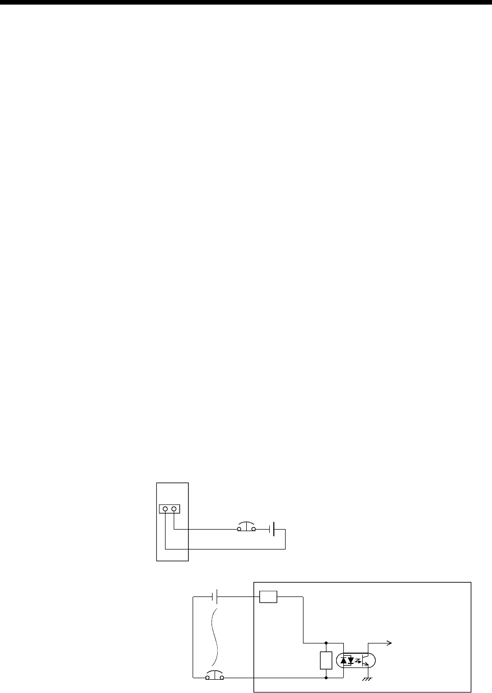
The wiring example for the forced stop input of Motion controller is shown
below.
R
R
EMI.COM
EMI
Forced stop
24VDC
(Note-1)
(Note): The forced stop input can not be invalidated in the system
settings.
(Note-1): As for the connection, both "+" and "-" are possible.
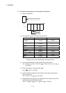
<Motion controller>
Q170M
CPU
24VDC
EMI
EMI.COM
Forced stop