


7 - 4
7 POSITIONING DEDICATED SIGNALS
7.2.2 Data Registers
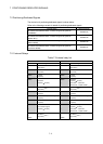
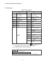
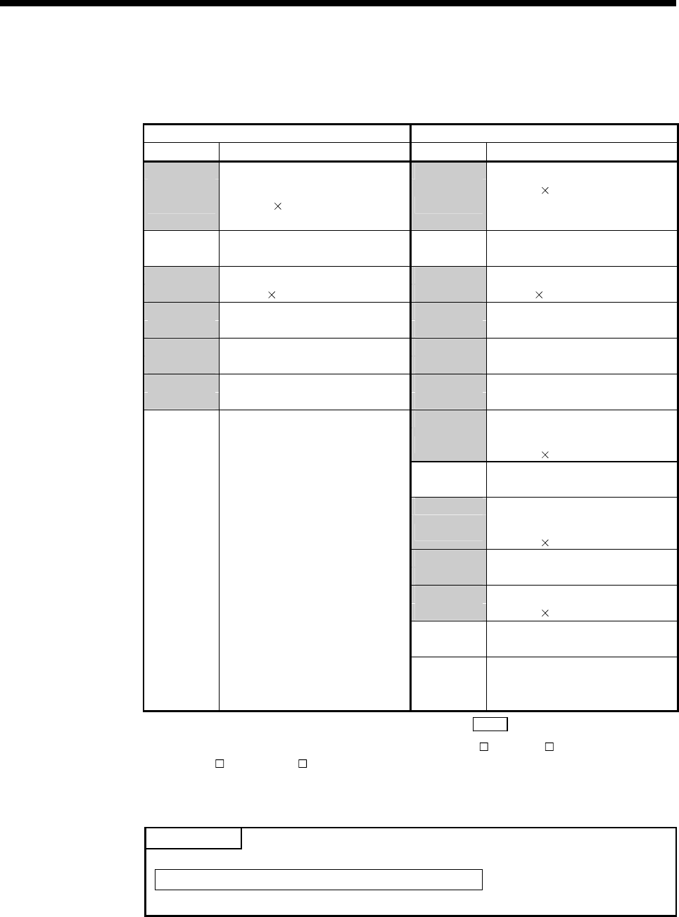
Table 7.3 Data register list
SV13 SV22
Device No. Application Device No. Application
D0 D0
to
Axis monitor device
(20 points
16 axes)
to
Axis monitor device
(20 points
16 axes)
Real mode……each axis
Virtual mode….output module
D320 D320
to
User device
(320 points)
(Note-1)
to
User device
(320 points)
(Note-1)
D640 D640
to
Control change register
(2 points
16 axes)
to
Control change register
(2 points
16 axes)
D672 D672
to
Unusable
(32 points)
to
Unusable
(32 points)
D704 D704
to
Common device (Command signal)
(54 points)
to
Common device (Command signal)
(54 points)
D758 D758
to
Unusable
(42 points)
to
Unusable
(42 points)
D800 D800
to
Virtual servo motor axis monitor
device
(10 points
16 axes)
(Note-2)
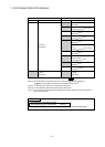
D960
to
User device
(160 points)
(Note-1)
D1120
to
Synchronous encoder axis monitor
device
(10 points 8 axes)
D1200
to
Unusable
(40 points)
D1240
to
CAM axis monitor device
(10 points
16 axes)
(Note-2)
D1400
to
User device
(160 points)
(Note-1)
D1560
to
to
D8191
User device
(7392 points)
D8191
User device
(6632 points)
It can be used as an user device.
(Note-1): When extending it to the system more than 17 axes in Q17 DCPU/Q17 HCPU(-T)/
Q17
CPUN(-T)/Q17 CPU, this device is recommended not to be used.
(Note-2): It can be used as an user device in the SV22 real mode only.
POINT
• Total number of user device points
7392 points (SV13) / 6632 points
(Note)
(SV22)
(Note): Up to 7272 points can be used when not using it in the virtual mode.