


2 - 56
2 SYSTEM CONFIGURATION
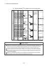
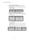
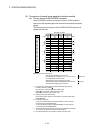
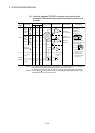
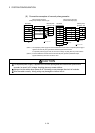
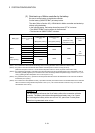
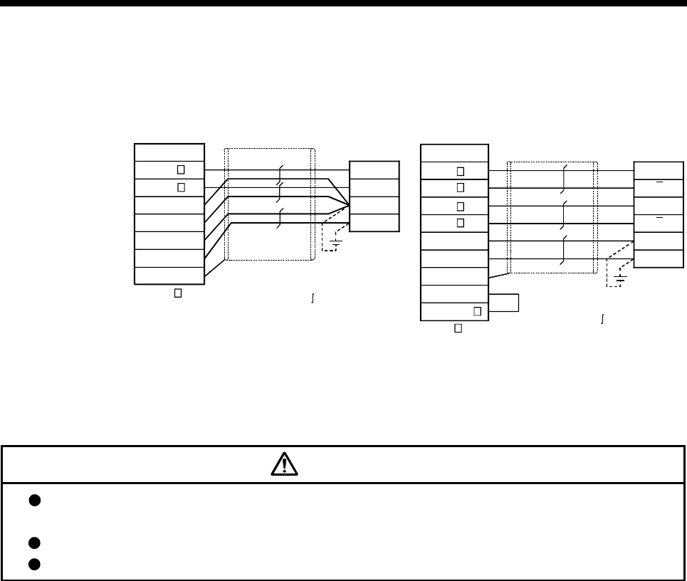
(6) Connection examples of manual pulse generator
SG
SG
Q173DPX
SG
P5
Signal name
A
B
0V
5V
Manual pulse
generator side
FG
Shield
: 1 to 3
HA
HB
(Note-1)
:Twisted pair cable
A
A
B
0V
5V
SG
P5
B
FG
SG
Q173DPX
Manual pulse
generator side
Signal name
: 1 to 3
HA P
HA N
HB P
HB N
HPSEL
(Note-2)
(Note-1)
:Twisted pair cable
Shield
Manual pulse generator
(Differential-output type)
Manual pulse generator
(Voltage-output/Open-collector type)
(Note-1) : The 5V(P5)DC power supply from the Q173DPX must not be used if a separate power supply is
applied to the manual pulse generator/incremental synchronous encoder.
If a separate power supply is used, be sure it is 5V voltage. Anything else may cause a failure.
(Note-2) : Connect HPSEL to the SG terminal if the manual pulse generator (differential-output
type)/incremental synchronous encoder is used.
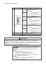
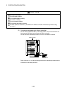
CAUTION
If a separate power supply is applied to the manual pulse generator/incremental synchronous
encoder, be sure it is 5V voltage. Anything else may cause a failure.
Always wire the cables when power is off. Not doing so may damage the circuit of modules.
Wire the cable correctly. Wrong wiring may damage the internal circuit.