


4 - 28
4 INSTALLATION AND WIRING
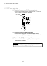
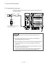
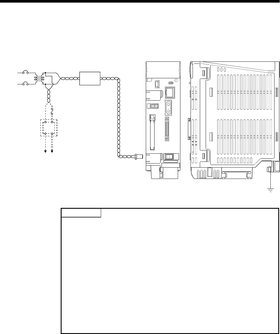
4.3.2 Connecting to the power supply
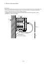
The following diagram shows the wiring example of power lines, grounding lines, etc.
to the Motion controller.
24VDC
+
-
AC DC
Fuse
100/200VAC 24VDC
AC
DC
FG
24VDC
Connect to power input terminals of I/O
signals that require 24VDC.
AC
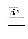
POINT
(1) Use a different 24VDC power supply for the Motion controller and for I/O
signals.
(2) Use a different 24VDC power supplies for the Motion controller and the
electromagnetic brake of the servo motor.
(3) Refer to Section 2.5.1(10) for the pin layout of 24VDC power supply connector,
and refer to APPENDIX 4.3 for the connection diagram of 24VDC power
supply cable.
(4) Motion controller and 24VDC power supply are an open type device and must
be installed in a control panel for use.
This not only ensures safety but also ensures effective shielding for Motion
controller and 24VDC power supply generated electromagnetic noise.