


2 - 53
2 SYSTEM CONFIGURATION
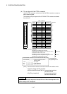
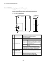
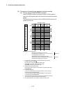
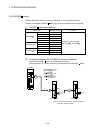
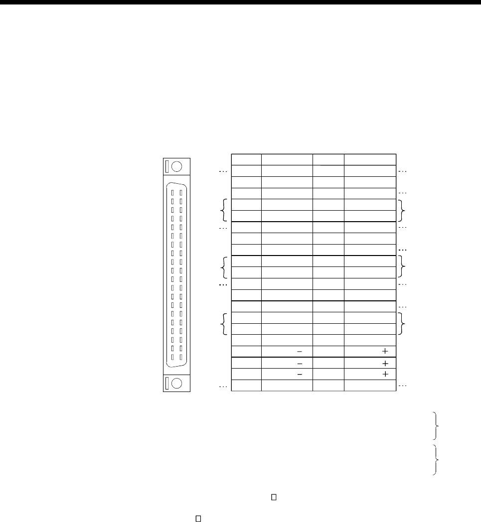
(5) Connection of manual pulse generator interface module
(a) The pin layout of the PULSER connector
Use the PULSER connector on the front of the Q173DPX module to
connect to manual pulse signals and incremental synchronous encoder
signals.
The following is the pin layout of the Q173DPX PULSER connector as
viewed from the front.
SG
HB1
Pin No.
B20
B19
B18
B17
Signal Name
5V
HA1N
PULSER connector
B16
B15
B14
B13
B12
B11
B10
B9
B8
B7
B6
B5
B4
B3
B2
B1
A20
A19
A18
A17
A16
A15
A14
A13
A12
A11
A10
A9
A8
A7
A6
A5
A4
A3
A2
A1
SG
HA1
HPSEL1
HA1P
HA2
HB1P
SG
HB2
HB1N
SG
5V
HA2N
HB2N
HB3
SG
5V
HA3N
HB3N
TREN1
TREN2
TREN3
FG
HPSEL2
HA2P
HA3
HB2P
SG
HPSEL3
HA3P
HB3P
TREN1
TREN2
TREN3
FG
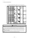
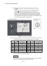
Pin No. Signal Name
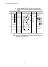
No connect
Input type from manual pulse generator/incremental synchronous
encoder switched by HPSEL .
Not connected : Voltage-output/open-collector type
HPSEL -SG connection : Differential-output type
(Switching is possible for each input 1 to 3)
1) :
4)
3)
2)
1)
3)
1)
3)
2)
1)
2)
4)
3)
2)
3)
2)
3)
2)
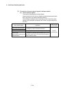
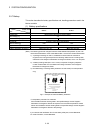
No connect
Voltage-output/open-collector type
Connect the A-phase signal to HA1/HA2/HA3, and the B-phase signal
to HB1/HB2/HB3.
2) :
Differential-output type
Connect the A-phase signal to HA1P/HA2P/HA3P, and the A-phase
inverse signal to HA1N/HA2N/HA3N.
Connect the B-phase signal to HB1P/HB2P/HB3P, and the B-phase
inverse signal to HB1N/HB2N/HB3N.
3) :
Connect the shield cable between manual pulse generator/incremental
synchronous encoder and Q173DPX at the FG signal.
4) :
Connector/terminal block conversion modules cannot be used.5) :
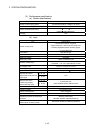
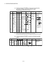
(Attachment)
(Optional)
A
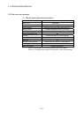
pplicable connector model name
A6CON2 type Crimp-contact type connector
A6CON3 type Pressure-displacement type connector
A6CON4 type soldering type connector
A6CON1 type soldering type connector
FCN-361J040-AU connector
(FUJITSU COMPONENT LIMITED)
FCN-360C040-B connector cover