


2 - 55
2 SYSTEM CONFIGURATION
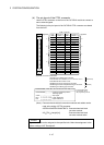
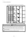
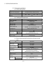
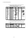
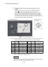
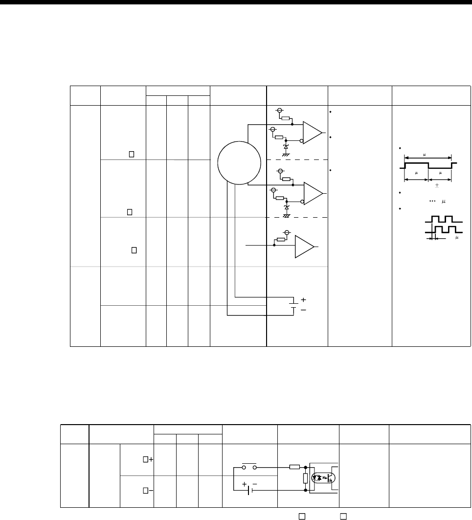
(c) Interface between PULSER connector and manual pulse
generator (Voltage-output/Open-collector type)/
Incremental synchronous encoder.
A
Manual pulse
generator/
Incremental
synchronous
encoder
Input or
Output
Signal name
Pin No.
Wiring example Internal circuit Specification Description
5V
Input
A20
A15 A10
Manual
pulse
generator,
phase A
B20 B15 B10
A18 A13 A8
Power
supply
P5
SG
B18 B13 B8
A19 A14 A9
B19 B14 B9
SG
No connect
Rated input voltage
5.5VDC or less
HIGH level
3 to 5.25VDC/
2mA or less
1VDC or less/
5mA or more
For connection
manual pulse
generator
Phases A, B
Pulse width
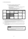
(1) Positioning address
increases if Phase A
leads Phase B.
Phase difference
B
Power supply
5VDC
123
Manual
pulse
generator,
phase B
HA
HB
LOW level
(2) Positioning address
decreases if Phase B
leads Phase A.
Select type
signal
HPSEL
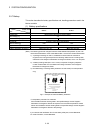
The 5V(P5)DC power supply from the Q170MCPU must not be used if a separate power supply is
applied to the manual pulse generator/incremental synchronous encoder.
If a separate power supply is used, be sure it is 5V voltage. Anything else may cause a failure
.
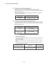
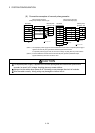
(Note) :
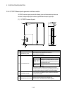
(Note)
Phase A
2.5 s or
Phase B
more
(Duty ratio: 50% 25%)
20 s or more
5 s
or more
5 s
or more
Leading edge, Trailing
edge time 1 s or less.
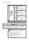
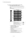
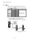
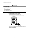
(d) Interface between PULSER connector and tracking enable
signal
Signal name Wiring example Internal circuit Specification Description
12V to 24VDC
Input or
Output
Tracking
enable
A4 A3 A2
B4 B3 B2
1 2 3
Tracking enable
signal input.
Input
TREN
TREN
Pin No.
(Note) : As for the connection to tracking enable (TREN +, TREN –), both "+" and "–" are possible.