


2 - 50
2 SYSTEM CONFIGURATION
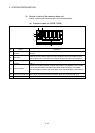
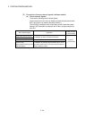
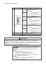
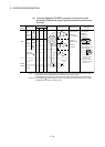
No.
Name Application
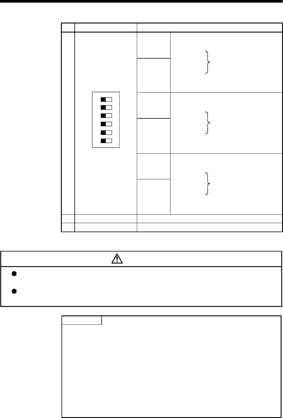
Detection setting of TREN1 signal
SW1 SW2
Dip switch 1
OFF OFF
ON ON
ON OFF
TREN is detected at leading
edge of TREN signal.
Dip switch 2
OFF ON
TREN is detected at trailing edge
of TREN signal.
Detection setting of TREN2 signal
SW3 SW4
Dip switch 3
OFF OFF
ON ON
ON OFF
TREN is detected at leading
edge of TREN signal.
Dip switch 4
OFF ON
TREN is detected at trailing edge
of TREN signal.
Detection setting of TREN3 signal
SW5 SW6
Dip switch 5
OFF OFF
ON ON
ON OFF
TREN is detected at leading
edge of TREN signal.
6)
Dip switches
(Note-1)
123456
ON
(Factory default in OFF
position)
Dip switch 6
OFF ON
TREN is detected at trailing edge
of TREN signal.
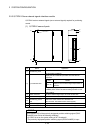
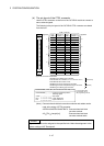
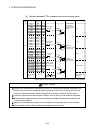
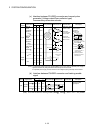
7) Module fixing projection Projection used to fix to the base unit.
8) Serial number display Display the serial number described on the rating plate.
(Note-1) : The function is different according to the operating system software installed.
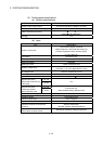
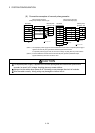
CAUTION
Before touching the DIP switches, always touch grounded metal, etc. to discharge static
electricity from human body. Failure to do so may cause the module to fail or malfunction.
Do not directly touch the module's conductive parts and electronic components. Touching them
could cause an operation failure or give damage to the module.
POINTS
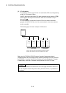
Input indicator LED of the manual pulse generator/incremental synchronous
encoder phases A, B and tracking enable signal turns ON at the following
conditions.
(1) PLS.A 1 to 3, PLS.B 1 to 3
• Q173DPX is set in the system setting of MT Developer2.
• All axes servo ON command (M2042) turned on.
• Manual pulse generator enable flag (M2051, M2052, M2053) turned on.
• Manual pulse generator signal is input.
(2) TREN 1 to 3
• Q173DPX is set in the system setting of MT Developer2.
• The tracking enable signal is input.