


2 - 29
2 SYSTEM CONFIGURATION
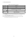
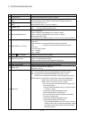
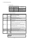
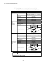
(7) Operation mode
(a) Rotary switch setting and operation mode
Rotary switch setting
SW1 SW2
Operation mode
A Any setting (Except C) Installation mode
0 0 Mode operated by RAM
0 6 Mode operated by ROM
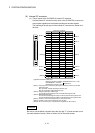
0 8 Ethernet IP address display mode
Any setting C SRAM clear
(Note)
(Note) : The data (Refer to Section 6.5) of RAM built-in Motion controller are cleared.
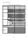
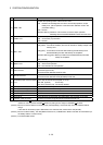
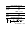
(b) Operation mode overview
Operation mode 7-segment LED Operation overview
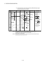
Installation mode
• Steady "INS" display at the 7-segment LED.
• Operating system software can be installed.
• It is STOP status regardless of the RUN/STOP/RESET switch position at the
front side of Motion controller.
• Digital oscilloscope function cannot be used.
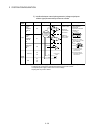
Mode operated by
RAM
• " . " remains flashing in the first digit of 7-segment LED.
• It operates based on the user programs and parameters stored in the RAM
built-in Motion controller.
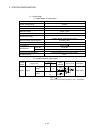
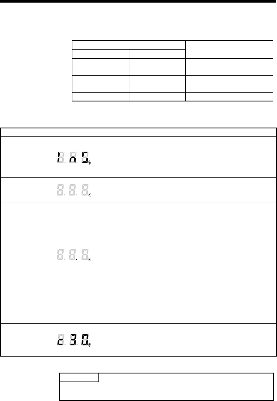
Mode operated by
ROM
• " . " remains flashing in the first digit and steady" . "display in the second digit
of 7-segment LED.
• Operation starts after the user programs and parameters stored in the FLASH
ROM built-in Motion controller are read to the RAM built-in Motion controller at
power supply on or reset of the Motion controller.
If the ROM writing is not executed, even if the user programs and parameters
are changed using the MT Developer2 during mode operated by ROM,
operation starts with the contents of the FLASH ROM built-in Motion controller
at next power supply on or reset.
Also, If the ROM writing is not executed, even if the auto tuning data are
reflected on the servo parameter of Motion controller by operation in the auto-
tuning setting, operation starts with the contents of the FLASH ROM built-in
Motion controller at next power supply on or reset.
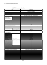
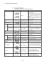
Ethernet IP address
display mode
Refer to next
page (c)
• Refer to next page "(c) Ethernet IP address display mode overview".
• Digital oscilloscope function cannot be used.
SRAM clear
• " . " remains flashing in the first digit of 7-segment LED.
• The data (Refer to Section 6.5) of RAM built-in Motion controller are cleared by
turning ON the Motion controller’s power supply after the rotary switch2 is set to
"C".
POINTS
Be sure to turn OFF the Motion controller's power supply before the rotary switch
setting change.