


APP - 3
A
PPENDICES
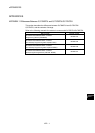
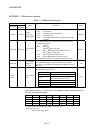
APPENDIX 1.2 Differences of parameters
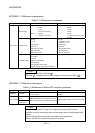
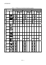
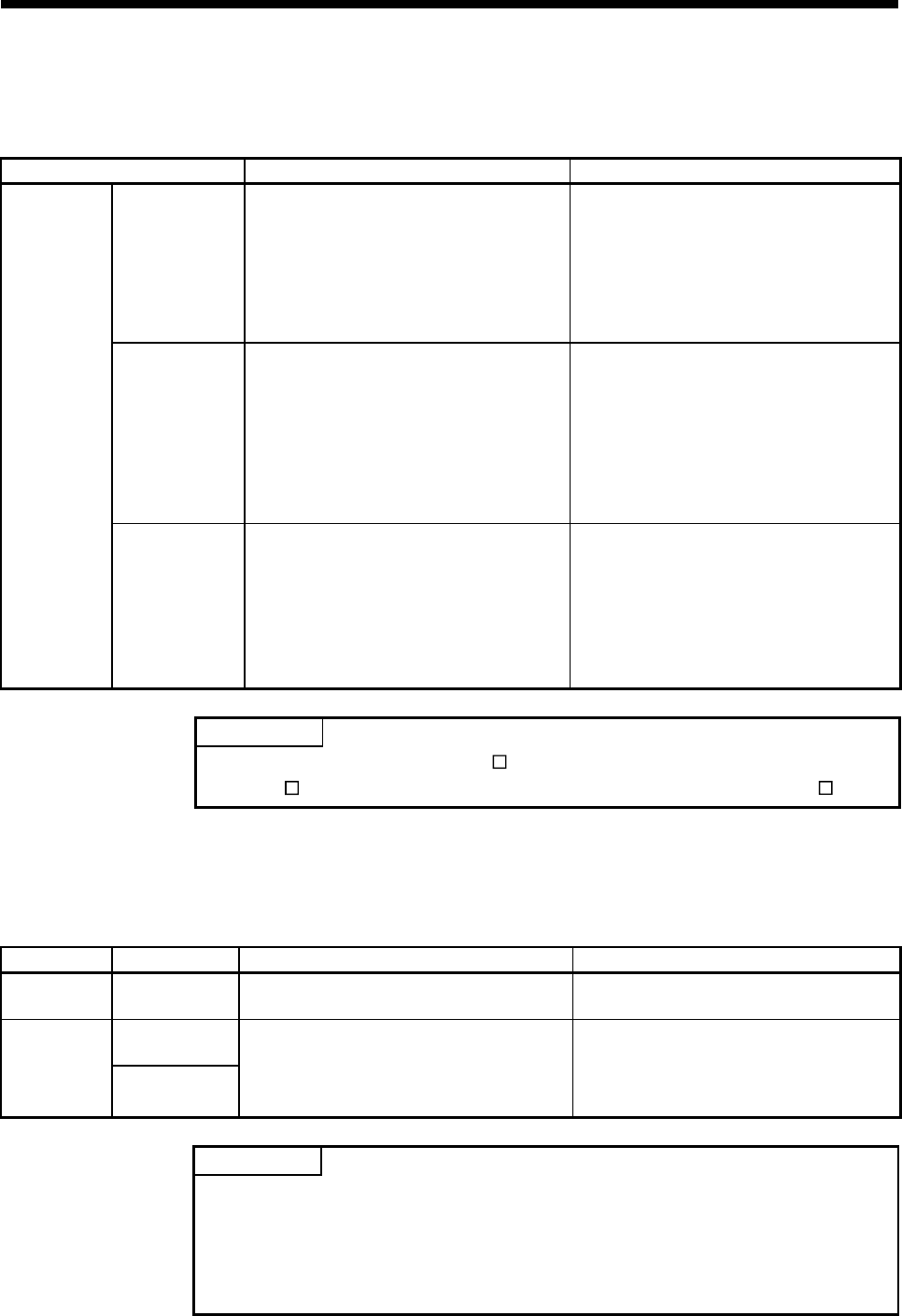
Table 1.2 Differences of parameters
Item Q170MCPU Q173DCPU/Q172DCPU
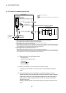
Extension base
Stage 1............Nothing
2 Slots
5 Slots
GOT (Bus connection)
Stage 2............Nothing
GOT (Bus connection)
Stage 1 to 7 ........Nothing
2 Slots
3 Slots
5 Slots
8 Slots
10 Slots/GOT (Bus connection)
12 Slots
Amplifier setting
[Axis No.]
1 to 16
[Amplifier type]
MR-J3-B
MR-J3-B Fully closed
MR-J3-B Linear
MR-J3-B DD motor
[Axis No.]
Q173DCPU: 1 to 32
Q172DCPU: 1 to 8
[Amplifier type]
MR-J3-B
MR-J3-B Fully closed
MR-J3-B Linear
MR-J3-B DD motor
System setting
Q170M I/O setting
Used/Unused
[First I/O No.]
0 to FF0
[High-speed read setting]
Used/Unused
[Input signal detection direction]
Valid on leading edge/Valid on trailing edge
—
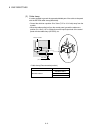
POINT
Set "MR-J3-B" to use the MR-J3W- B.
MR-J3W-
B is recognized as two servo amplifiers. Set two axes as MR-J3- B.
APPENDIX 1.3 Differences of programs
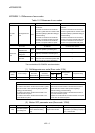
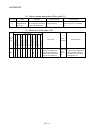
Table 1.3 Differences of Motion SFC and servo programs
Program Item Q170MCPU Q173DCPU/Q172DCPU
Motion SFC Event task
Fixed cycle (0.44ms, 0.88ms, 1.77ms, 3.55ms,
7.11ms, 14.2ms).
Fixed cycle (0.88ms, 1.77ms, 3.55ms, 7.11ms,
14.2ms)
Speed-position
control
Servo program
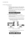
Count type home
position return
DOG/CHANGE signal of Q172DLX and external
input signal (DOG) of servo amplifier can be used.
DOG/CHANGE signal of Q172DLX can be used.
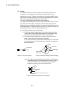
POINT
The variation for ON/OFF timing of the external input signal (DOG) of servo
amplifier may occur according to the input filter setting value of external signal input
setting.
Review the input filter setting value compatible with the applications.
Use the Q172DLX to execute the high-accuracy control.