


2 - 37
2 SYSTEM CONFIGURATION
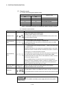
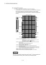
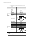
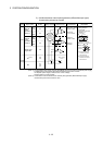
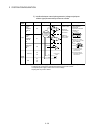
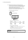
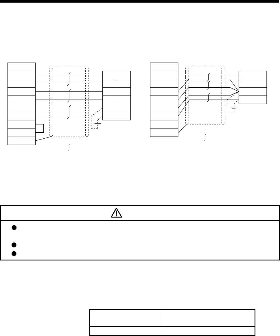
4) Connection examples of manual pulse generator/incremental
synchronous encoder
(Note-1): The 5V(P5)DC power supply from the Q170MCPU must not be used if a separate power
supply is applied to the manual pulse generator/incremental synchronous encoder.
If a separate power supply is used, be sure it is 5V voltage. Anything else may cause a failure.
(Note-2): Input type from manual pulse generator/incremental synchronous encoder switched by SEL.
Not connected: Voltage-output/open-collector type
SEL-SG connection: Difference-output type
HBH
SG
SG
HAH
5V
HBL
HAL
SEL
Voltage-output/Open-collector typeDifferential-output type
Q170MCPU
Manual pulse generator/
Incremental synchronous
encoder side
Manual pulse generator/
Incremental synchronous
encoder side
Q170MCPU
Signal name
Shell
Shield
: Twist pair cable
B
A
0V
5V
A
B
SG
SEL
SG
HA
5V
SG
HB
Shell
Signal name
B
A
0V
5V
: Twist pair cable
Shield
(Note-2)
(Note-1)
(Note-1)
CAUTION
If a separate power supply is applied to the manual pulse generator/incremental synchronous
encoder, be sure it is 5V voltage. Anything else may cause a failure.
Always wire the cables when power is off. Not doing so may damage the circuit of modules.
Wire the cable correctly. Wrong wiring may damage the internal circuit.
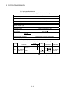
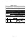
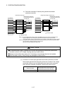
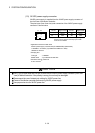
(e) Connection of manual pulse generator/incremental synchronous encoder
Manual pulse generators/incremental synchronous encoders of the voltage-
output/open-collector type and differential-output type can be connected.
Both connection methods are different. (Refer to this section (8)(a).)
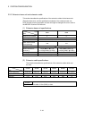
Motion controller
Connectable manual pulse generator/
incremental synchronous encoder
Q170MCPU (Internal I/F) Up to 1 module