


3 - 1
3 DESIGN
3. DESIGN
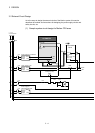
3.1 System Designing Procedure
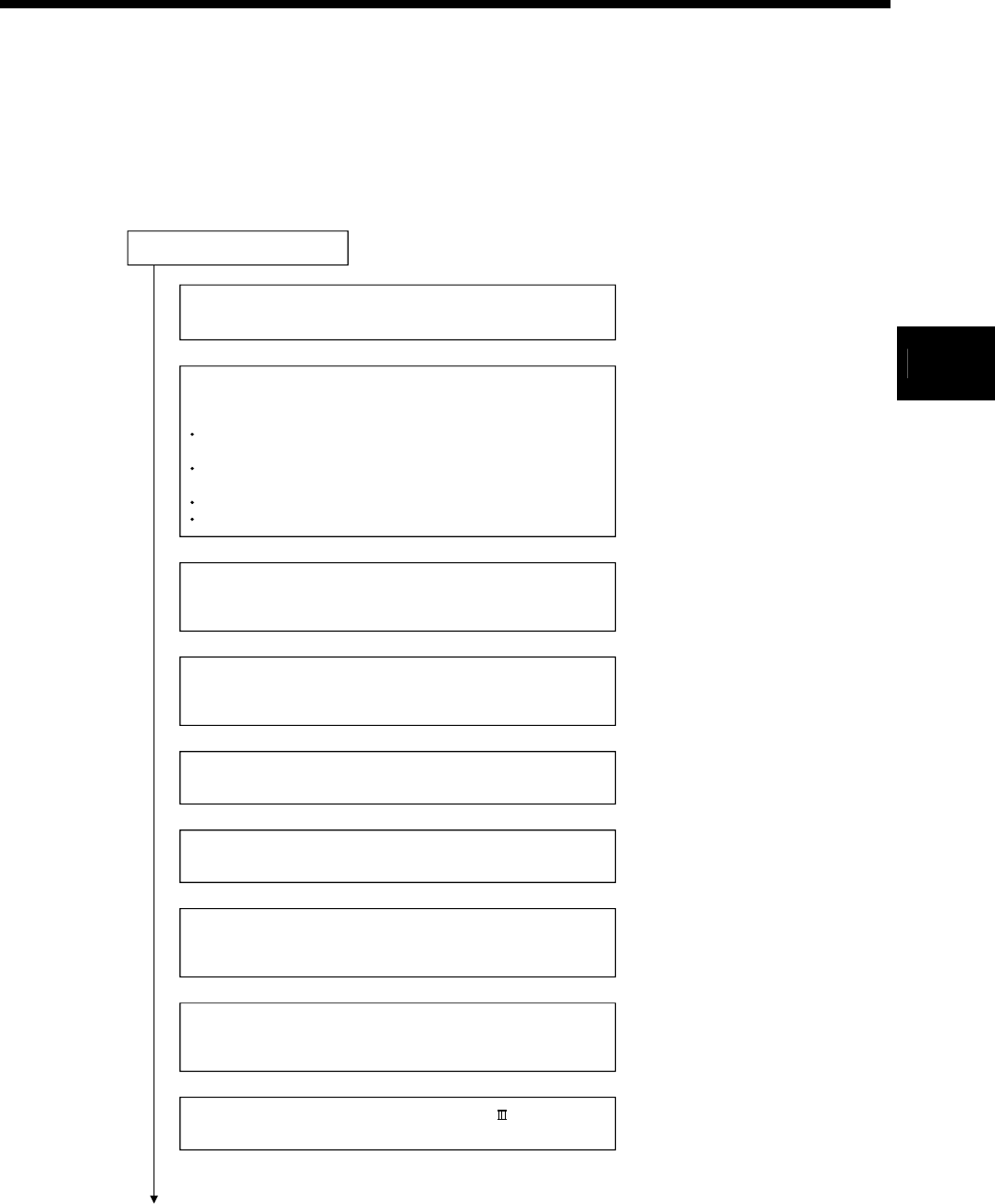
System designing procedure is shown below.
Motion control system design
Select the operating system software to be installed according
to the machinery and equipment to be controlled.
Refer to section 2.5.3
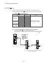
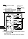
Select the number of Q172DLX's and design according to the
each axis control system and whether servo external signals are
required or not.
When there is mechanical home position and home position
return is made: Proximity dog required
For speed control: Speed-position switching control signal
required
When overrun prevention is necessary: Stroke limit required
When each axis stop is necessary: STOP signal required
Select Q173DPX and design according to whether manual pulse
generators and incremental synchronous encoders are required
or not.
Refer to section 2.5.4
Select interrupt module QI60 according to whether interrupt
input are required or not.
Select I/O modules/intelligent function modules according to the
specifications of the external equipment to be controlled.
Refer to MELSEC-Q
series manual.
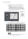
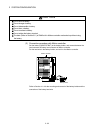
Select the extension base units/extension cables, and make
I/O assignment according to necessary number of Q172DLXs,
Q173DPXs, I/O modules, intelligent function modules.
Refer to section 2.5.3
Refer to section 2.5.4
Refer to MELSEC-Q
series manual.
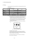
Select the servo amplifier and servo motor according to the
motor capacity and number of revolution from the machine
mechanism to be controlled each axis.
Set the servo amplifier connection by SSCNET and axis
numbers (dno.) and axis No..
Refer to section 2.5.6
Refer to the servo
amplifier manual.
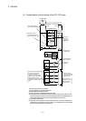
Select whether the manual pulse generators, incremental
synchronous encoders or I/O signals built-in Motion controller
are required or not.
Refer to section 2.5.1
3