


2 - 4
2 SYSTEM CONFIGURATION
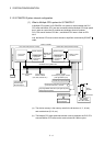
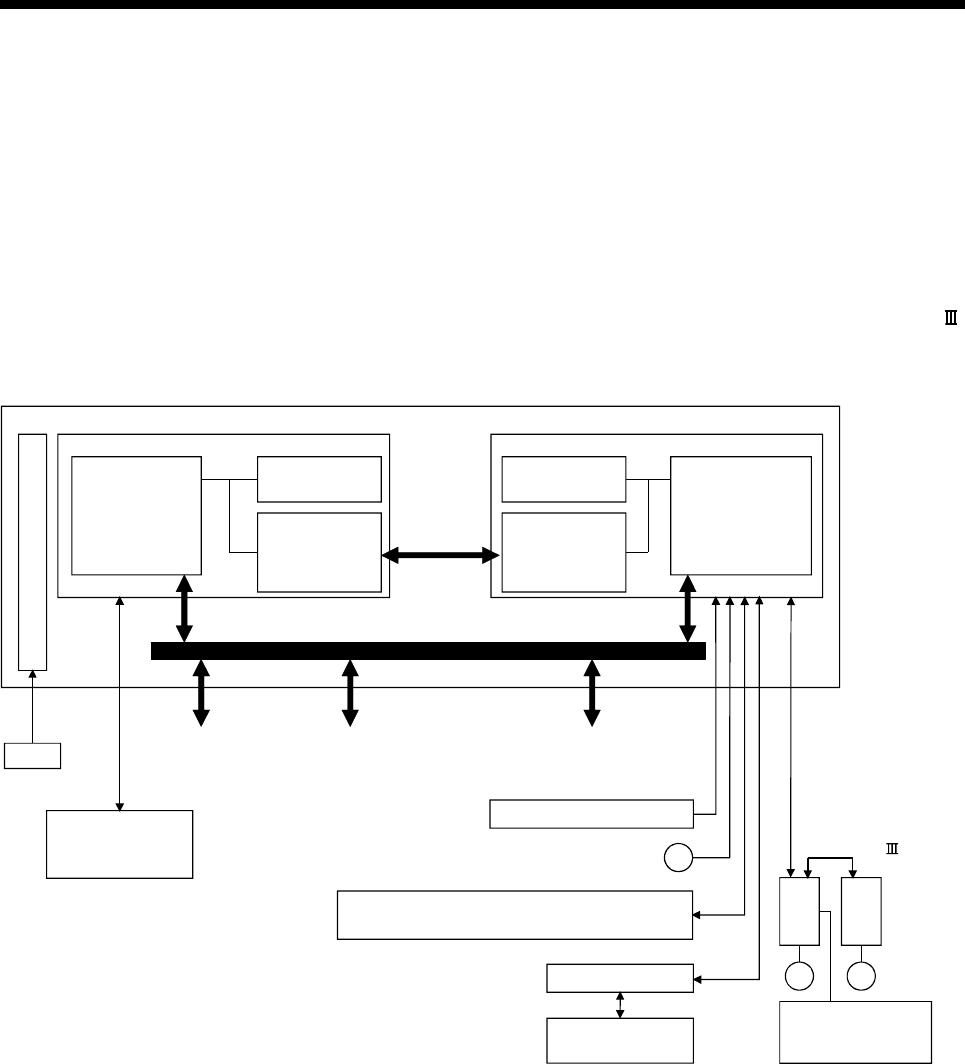
2.1.2 Q170MCPU System internal configuration
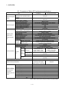
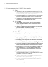
(1) What is Multiple CPU system for Q170MCPU ?
A Multiple CPU system for Q170MCPU is a system in which between the PLC
CPU area and Motion CPU area are connected with the Multiple CPU high speed
bus in order to control the I/O modules and intelligent function modules.
PLC CPU area is fixed as CPU No.1, and Motion CPU area is fixed as CPU
No.2.
And, the Motion CPU area controls the servo amplifiers connected by SSCNET
cable.
Multiple CPU
high speed
transmission
memory
M
Personal computer
GX Developer
MT Developer2
M
24VDC
PERIPHERAL I/F
Device memory Device memory
Multiple CPU
high speed
bus
Multiple CPU
high speed
transmission
memory
PLC control
processor
Motion control
processor
Q series PLC system bus
PLC I/O module
(DI/O)
PLC intelligent
function module
(A/D, D/A, Network etc.)
Motion module
(Proximity dog signal, manual
pulse generator input)
Servo
amplifier
Servomotor
Motion controller
Personal computer
MT Developer2
Forced stop input (24VDC)
Servo external
input signals
(FLS, RLS, DOG)
Power supply
SSCNET
PLC CPU area (CPU No.1 fixed) Motion CPU area (CPU No.2 fixed)
Manual pulse generator/Incremental
synchronous encoder 1 module
Input signal/Mark detection input signal (4 points)
Output signal (2 points)
P
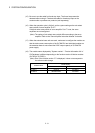
(a) The device memory is the memory area for the bit devices (X, Y, M, etc.)
and word devices (D, W, etc.).
(b) The Multiple CPU high speed transmission memory between the PLC CPU
area and Motion CPU area can be communicated at 0.88ms cycles.