


APP - 31
A
PPENDICES
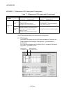
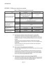
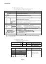
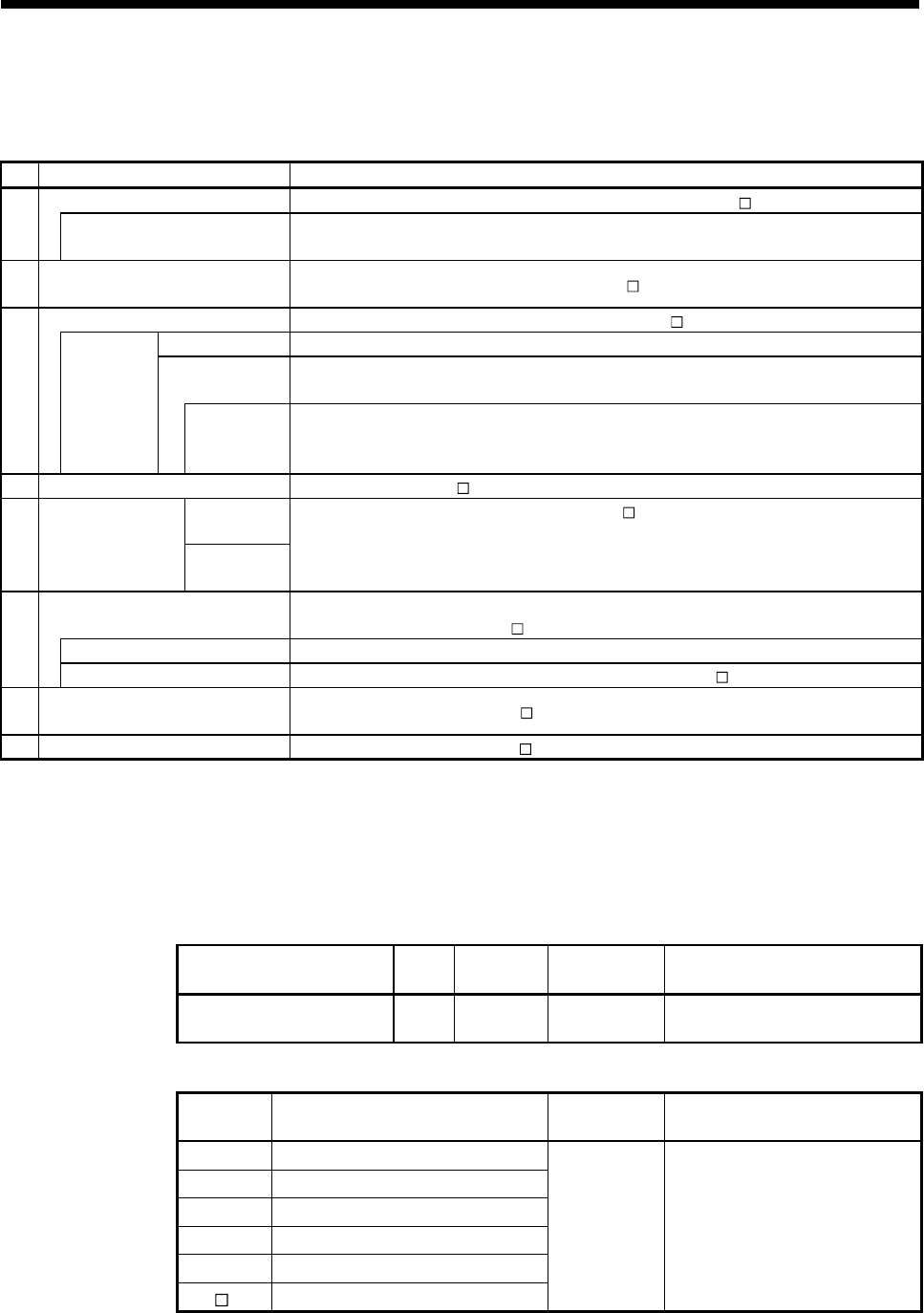
(2) Mark detection setting
The mark detection setting parameters are shown below.
Up to 32 mark detections setting can be registered.
No. Item Setting range
Mark detection signal Q170MCPU's internal I/F (DI)/Device (Bit device (X, Y, M, B, SM, U \G))
1
Mark detection signal detection
direction
(Note-1)
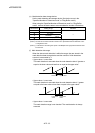
Valid on leading edge/Valid on trailing edge
2
Mark detection signal compensation
time
(Note-2)
-5000000 to 5000000[µs]/Word device (D, W, #, U
\G)
Mark detection data Motion control data/Device (Word device (D, W, #, SD, U \G))
Data type 16-bit integer type/32-bit integer type/64-bit floating-point type
Estimate
calculation
Valid (Normal data)/Valid (Ring counter)/Invalid
3
At device
selection
Ring counter
value
16-bit integer type : K1 to K32767, H001 to H7FFF
32-bit integer type : K1 to K2147483647, H00000001 to H7FFFFFFF
64-bit floating-point type : K2.23E-308 to K1.79E+308
4 Mark detection data storage device Word device (D, W, #, U \G)
Upper value
5
Mark detection data
range
Lower value
Direct designation (K, H)/Word device (D, W, #, U
\G)
16-bit integer type : K-32768 to K32767, H0000 to HFFFF
32-bit integer type : K-2147483648 to K2147483647, H00000000 to HFFFFFFFF
64-bit floating-point type : K-1.79E+308 to K-2.23E-308, K0, K2.23E-308 to K1.79E+308
Mark detection mode setting
Continuous detection mode/Specified number of detection mode/Ring buffer mode/
Device (Word device (D, W, #, U
\G))
Number of detections 1 to 8192 (Specified number of detection mode/Ring buffer mode)
6
Mark detection times counter
—
(Note-3)
(Continuous detection mode)/Word device (D, W, #, U \G)
7
Mark detection current value
monitor device
—
(Note-3)
/Word device (D, W, #, U \G)
8 Mark detection signal status
—
(Note-3)
/Bit device (X, Y, M, B, U \G)
(Note-1): Set the input signal detection direction of Q170MCPU's internal I/F (DI) in the "Q170M I/O Setting" of System Settings.
(Note-2): The mark detection signal compensation time cannot be set if "Invalid" is selected in the estimate calculation. (0[µs] is set.)
(Note-3): This setting can be ignored.
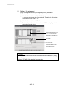
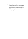
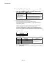
(a) Mark detection signal
Set the input signal for mark detection.
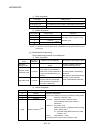
1) Module input signal
Input module Signal Signal No.
Detection
accuracy [µs]
Signal detection direction
(Leading edge/Trailing edge)
Q170MCPU's internal I/F DI 1 to 4 30
Set direction in the "Q170M I/O
Setting" of System Settings.
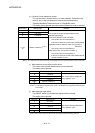
2) Bit device
Bit device Setting range
Detection
accuracy [µs]
Signal detection direction
(Leading edge/Trailing edge)
X(PX) 0 to 1FFF
Y(PY) 0 to 1FFF
M 0 to 8191
B 0 to 1FFF
SM 0 to 1999
U \G
10000.0 to (10000+p-1).F
(Note-1)
444
Set direction in the mark
detection signal detection
direction.
(Note-1): "p" indicates the user setting area points of the Multiple CPU high speed transmission area for each
CPU.