


Software Developer’s Manual 85
PCI Local Bus Interface
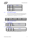
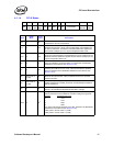
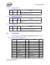
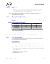
4.1.3.1.4 Message Address
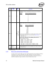
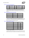
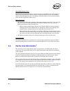
4.1.3.1.5 Message Upper Address
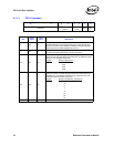
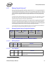
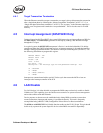
4.1.3.1.6 Message Data
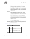
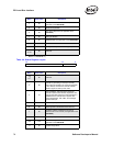
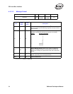
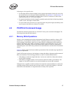
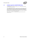
4.2 Commands
The Ethernet controller is capable of decoding and encoding commands for both PCI and PCI-X
modes. The difference between PCI and PCI-X commands is noted in Table 4-5.
Bits
Read/
Write
Initial
Value
Description
31:0 RW 0b
Message Address – Written by the system to indicate the lower 32-
bits of the address to use for the MSI memory write transaction. The
lower two bits are always written as 0b.
Bits
Read/
Write
Initial
Value
Description
31:0 RW 0b
Message Upper Address – Written by the system to indicate the
upper 32-bits of the address to use for the MSI memory write
transaction.
Bits
Read/
Write
Initial
Value
Description
15:0 RW 0b
Message Data – Written by the system to indicate the lower 16 bits of
the data written in the MSI memory write DWORD transaction. The
upper 16 bits of the transaction are written as 0b.
Table 4-5. PCI and PCI-X Encoding Difference
C/BE
Encoding
PCI Commands Abr. PCI-X Commands Abr.
0h Interrupt Acknowledge Interrupt Acknowledge
1h Special Cycle Special Cycle
2h I/O Read IOR I/O Read IOR
3h I/O Write IOW I/O Write IOW
4h Reserved Reserved
5h Reserved Reserved
6h Memory Read MR Memory Read DWORD MRD
7h Memory Write MW
8h Reserved Alias to MRB AMR
9h Reserved Alias to MWB AMW
Ah Configuration Read CFR Configuration Read CFR
Bh Configuration Write CFW Configuration Write CFW
Ch Memory Read Multiple MRM Split Completion SC