


108 Software Developer’s Manual
EEPROM Interface
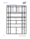
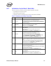
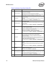
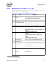
Bit Name Description
8 MAC Clock Speed
82541PI/GI Only.
0b = MAC runs at full speed.
1b = MAC runs at 1/4 speed on any drop from 1000 Mb/s.
Note: Reserved bit for all other Ethernet controllers (set to 0b). Formally
FLASH Disable, now located in Initialization Control Word 3, bit 3.
7 MSI Disable
When set to 0b (default), enables Message Signalled Interrupts (MSI) in
standard PCI mode.
When set to 1b, disables Message Signalled Interrupts (MSI) in standard
PCI mode.
Note: Reserved bit for the 82541xx and 82547GI/EI (set to 1b).
6 133 MHz Capable
When set to 1b (default), maps the 133 MHz Capable bit of the PCI-X
Status Register (PCIXS).
When set to 0b, does not map the 133 MHz Capable bit of the PCI-X Status
Register (PCIXS).
Note: Reserved bit for the 82541xx, 82547GI/EI, and 82540EP/EM (set to
0b).
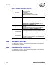
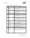
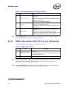
5 DMCR_Map
Indicates how the Designed Maximum Cumulative Read size bits in the
PCI-X Status register are mapped.
When set to 1b (default), the DMCR value reflects the hard-coded design
capability as indicated by the Max_Read bit (bit 4).
When set to 0b, the DMCR is mapped directly to the Maximum Memory
Read Byte Count indicated in the PCI-X Command register.
Note: Reserved bit for the 82541xx, 82547GI/EI, and 82540EP/EM (set to
0b).
4 Max_Read
Indicates the maximum read value as advertised in the Designed Maximum
Memory Read Byte Count field in the PCI-X Status Register.
When set to 0b (default), or if there is no EEPROM, the advertised
maximum read is 2 KB.
When set to 1b, the advertised maximum read is 4 KB. Note that it is not
recommended to set Max_Read to 1b because transmit FIFO overruns are
possible under specific operating conditions.
Note: Reserved bit for the 82541xx, 82547GI/EI, and 82540EP/EM (set to
0b).
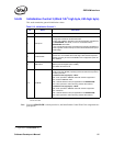
3 64-bit
When set to 1b (default), loads the 64-bit Device field of the PCI-X Status
Register.
When set to 0b, does not load the 64-bit Device field of the PCI-X Status
Register.
Note: Reserved bit for the 82541xx, 82547GI/EI, and 82540EP/EM (set to
0b).
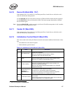
2 Reserved
Reserved for future use (set to 0b). Formerly APM Enable, now located in
Initialization Control Word 3, bit 2.
Note: Set to 1b for the 82541xx and 82547GI/EI.
1 Force CSR Read Split
When set to 0b (default), certain critical registers are decoded for non-split
access.
When set to 1b, forces all Ethernet controller control/status register-reads
to be split when operating in a PCI-X environment.
Note: Reserved bit for the 82541xx and
82547GI/EI (set to 0b).
0 Reserved Reserved for future use (set to 0b).
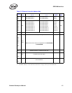
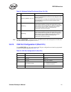
Table 5-6. Initialization Control Word 2 (Word 0Fh)