


Software Developer’s Manual 133
Power Management
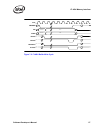
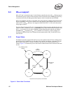
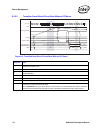
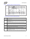
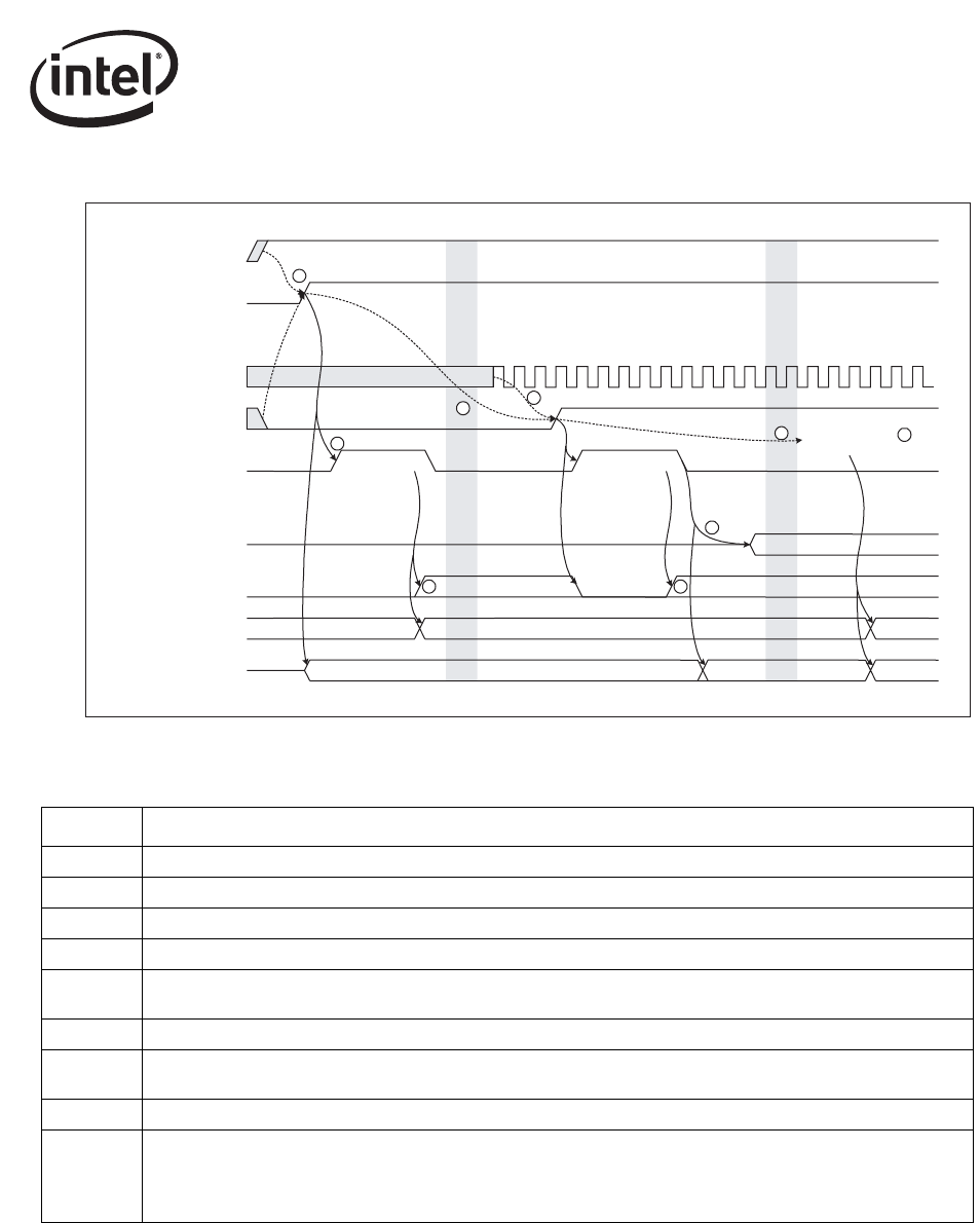
6.3.2.1 Power Up (Off to Dr to D0u to D0a)
Figure 6-2. Startup Timing
3RZHU
LAN_POWER_GOOD
CLK#
RST#
DState
3:5B67$7(>@
D0u
Reading EEPROM Read EEPROM
D0a
ELIZDNHXSLVGLVDEOHGELIZDNHXSLVHQDEOHG
E
Memory Access
1
PCI Pins
Running
Wakeup Enabled
Dr
2
E
APM Wakeup APM Wakeup
4
5
8
9
Read EEPROM
7
3
6
*&(,2QO\
Diagram # Notes
1 LAN_PWR_GOOD must not be asserted until all power supplies are good and the clock is stable.
2 An EEPROM read starts on the rising edge of LAN_PWR_GOOD and RST#.
3 APM Wakeup mode can be enabled based on what is read from the EEPROM.
4 The system can delay an arbitrary time before deasserting RST#.
5
The PCI 2.2 or 2.3 specification requires the clock to be active 100 µs before deasserting RST#. (T
clk-rst
parameter)
6 The deassertion edge of RST# causes the EEPROM to be re-read and Wakeup disabled.
7
Synchronizing the clock generators and circuit adjustments require up to 512 PCI clocks before the Ethernet
controller drives PCI signals and responds to PCI transactions.
8 The system can delay an arbitrary time before enabling Memory Access.
9
Writing a 1b to the Memory Access Enable or I/O Access Enable bit in the PCI Command Register transitions the
Ethernet controller from D0u to D0 state.
For the 82544GC/EI, writing a 1b to the Memory Access Enable or I/O Access Enable bit in the PCI Command
Register transitions the Ethernet controller from D0u to D0 state and asserts both PWR_STATE outputs.