


Receive and Transmit Description
Software Developer’s Manual 27
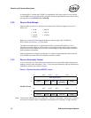
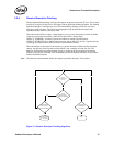
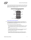
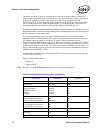
The receive descriptor head and tail pointers reference 16-byte blocks of memory. Shaded boxes in
the figure represent descriptors that have stored incoming packets but have not yet been recognized
by software. Software can determine if a receive buffer is valid by reading descriptors in memory
rather than by I/O reads. Any descriptor with a non-zero status byte has been processed by the
hardware, and is ready to be handled by the software.
Figure 3-2. Receive Descriptor Ring Structure
Note: The head pointer points to the next descriptor that is written back. At the completion of the
descriptor write-back operation, this pointer is incremented by the number of descriptors written
back. HARDWARE OWNS ALL DESCRIPTORS BETWEEN [HEAD AND TAIL]. Any
descriptor not in this range is owned by software.
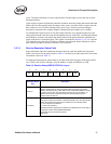
The receive descriptor ring is described by the following registers:
• Receive Descriptor Base Address registers (RDBAL and RDBAH)
These registers indicate the start of the descriptor ring buffer. This 64-bit address is aligned on
a 16-byte boundary and is stored in two consecutive 32-bit registers. RDBAL contains the
lower 32-bits; RDBAH contains the upper 32 bits. Hardware ignores the lower 4 bits in
RDBAL.
• Receive Descriptor Length register (RDLEN)
This register determines the number of bytes allocated to the circular buffer. This value must
be a multiple of 128 (the maximum cache line size). Since each descriptor is 16 bytes in
length, the total number of receive descriptors is always a multiple of 8.
• Receive Descriptor Head register (RDH)
This register holds a value that is an offset from the base, and indicates the in–progress
descriptor. There can be up to 64K descriptors in the circular buffer. Hardware maintains a
shadow copy that includes those descriptors completed but not yet stored in memory.
Circular Buffer Queues
Head
Base + Size
Base
Receive
Queue
Tail
Owned By
Hardware