


208 Software Developer’s Manual
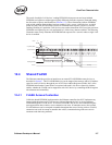
Dual Port Characteristics
Note: Access contention to FLASH by both LAN devices is more than likely to result in indeterminate
data results (during read transactions), corrupted FLASH (during write transactions), or other
unpredictable behavior.
To avoid this contention, accesses from both LAN devices MUST be synchronized using external
software synchronization of the memory or I/O transactions responsible for the access. It might be
possible to ensure contention-avoidance simply by nature of software sequentially.
12.5 LAN Disable
For a LOM design, it might be desirable for the system to provide BIOS-setup capability for
selectively enabling or disabling LOM devices. This might allow an end-user more control over
system resource-management, avoid conflicts with add-in NIC solutions, etc. The Ethernet
controller provides support for selectively enabling or disabling one or both LAN device(s) in the
system.
12.5.1 Overview
Device presence (or non-presence) must be established early during BIOS execution in order to
ensure that BIOS resource-allocation (of interrupts, of memory or IO regions) is done according to
devices that are present only. This is frequently accomplished using a BIOS CVDR (Configuration
Values Driven on Reset) mechanism. The Ethernet controller LAN-disable mechanism is
implemented in order to be compatible with such a solution. The Ethernet controller samples two
pins (FLASH data pins, bits 1 and 0) on reset to determine the LAN-enable configuration.
When a particular LAN is disabled, all internal clocks to that LAN are disabled, the device is held
in reset, and the internal PHY for that LAN is powered-down. The device does not respond to PCI
configuration cycles. Effectively, the LAN device becomes invisible to the system from both a
configuration and power-consumption standpoint.
Note: Since the LAN-disable mechanisms is implemented using the FLASH data pins, this mechanism
can only be used when no FLASH device is present (FLASH disabled). An Ethernet controller-
based NIC built with support for a FLASH device always enables both LAN devices.
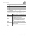
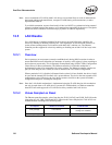
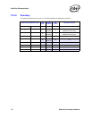
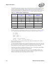
12.5.2 Values Sampled on Reset
The Ethernet controller samples values from the pins FLSH_DATA[1] and FLSH_DATA[0] on the
rising edge of LAN_PWR_GOOD and RST#. Based on the values sampled, the LAN devices are
enabled/disabled according to the following table:
Pin sampled LAN device controlled Enable/Disable
FLSH_DATA[0] LAN A device
Vcc/logic 1b = enabled
Vss/logic 0b = disabled
FLSH_DATA[1] LAN B device ???