


236 Software Developer’s Manual
Register Descriptions
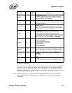
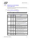
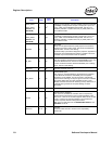
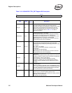
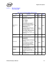
Table 13-12. 82544GC/EI CTRL_EXT Register Bit Description
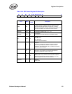
31 16 15 0
Reserved Extended Device Control Bits
Field Bit(s)
Initial
Value
Description
GPI_EN 3:0 0
General Purpose Interrupt Enables
These bits determine whether the upper three software
definable pins SDP[7:6] and SDP[4] are mapped to the ICR.GPI
interrupt bits. These mappings are enabled only when the
SDP[7:6] and SDP[4] pins are configured as inputs through
CTRL_EXT.SWDPIOHI. Refer to Table 13-13 for SDP to
ICR.GPI bit mapping.
SWDPINSHI 7:6, 4 0
Software Defined Pins – high nibble
These three bits allow direct control of SDP[7:6] and SDP[4].
These pins can be either input pins or output pins as
determined by the SWDPIOHI bits. The initial direction of the
software defined pins is read out of the EEPROM.
Note: SDP[5] and its associated bit is not used. It should be
programmed to 0b for future compatibility.
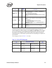
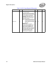
SWDPIOHI 11:10, 8 0
Software Defined Pins Input or Output
These three bits control whether each of the high nibble
software defined pins SDP[7:6] and SDP[4] is used as an input
or an output.
0b = inputs; 1b = outputs.
This field is not affected by assertion of software reset
(CTRL.RST).
Configurable through EEPROM.
Note: SDP[5] and its associated bit is not used. It should be
programmed to 0b for future compatibility.
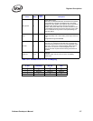
ASDCHK 12 0
ASD Check
Initiate an Auto-Speed-Detection (ASD) sequence to sense the
frequency of the PHY receive clock. The results are reflected in
STATUS.ASDV. This bit is self-clearing.
This functionality is provided for diagnostic purposes,
regardless of whether the Auto Speed Detection feature is
enabled. This bit is applicable only for internal PHY mode of
operation.
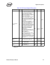
EE_RST 13 0
EEPROM Reset
When set, initiates a “reset-like” event to the EEPROM function.
This causes the EEPROM to be read as if a RST# assertion had
occurred. All Ethernet controller functions should be disabled
prior to setting this bit. This bit is self-clearing.
IPS 14 0
Invert Power State Bit 0
When set to 1b, inverts the assertion polarity of the
PWR_STATE bit 0 output. When cleared to 0b, PWR_STATE is
logic high in normal operation.
Configurable through EEPROM.