


Software Developer’s Manual 111
EEPROM Interface
Note: Since the 82546GB/EB is a dual-port device, the SDP control in 10h corresponds to LAN B, and
the SDP control in 20h corresponds to LAN A.
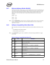
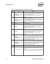
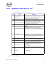
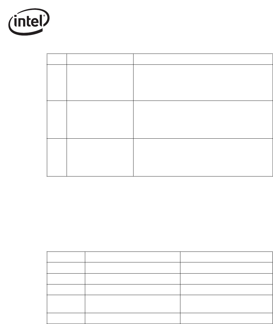
5.6.18 CSA Port Configuration 2 (Word 21h)
For the 82547GI/EI only, this word controls the CSA port configuration and must be programmed
to 93A7h for regular operation (see Table 5-9).
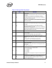
Table 5-9. CSA Port Configuration 2 (Word 21h)
Bit Name Description
2 D3COLD_WAKEUP_ADV_EN
Set this bit to 1b (default) to configure the initial hardware default
value of the ADVD3WUC bit in the Device Control Register (CTRL)
following power up.
Set this bit to 0b to not configure the initial hardware default value
of the ADVD3WUC bit in the Device Control Register (CTRL)
following power up.
1 SDPVAL[1]
SDP1 Pin - Initial Output Value.
Set this bit to 0b (default) to configure the initial power-on value
output on SDP1 (when configured as an output) by configuring the
initial hardware value of the SDP1_DATA bit in the Extended
Device Control Register (CTRL_EXT) after power up.
Set this bit to 1b if used as an output.
0 SDPVAL[0]
SDP0 Pin - Initial Output Value.
Set this bit to 0b (default) to configure the initial power-on value
output on SDP0 (when configured as an output) by configuring the
initial hardware value of the SDP0_DATA bit in the Extended
Device Control Register (CTRL_EXT) after power up.
Set this bit to 1b if used as an output.
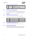
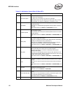
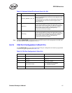
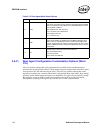
Table 5-8. Software Defined Pins Control (Word 10h, 20h)
Bit Description Default
15:13 Reserved. Set to 100b.
12 Reserved. Set to 1b.
11:2 Reserved. Set to 0011101001b.
1 Dock/Undock Polarity.
1b = Indicates Docked (default).
0b = Indicates Undocked.
0 Reserved. Set to 1b.