


Software Developer’s Manual 15
Architectural Overview
2.5 Ethernet Addressing
Several registers store Ethernet addresses in the Ethernet controller. Two 32-bit registers make up
the address: one is called “high”, and the other is called “low”. For example, the Receive Address
Register is comprised of Receive Address High (RAH) and Receive Address Low (RAL). The least
significant bit of the least significant byte of the address stored in the register (for example, bit 0 of
RAL) is the multicast bit. The LS byte is the first byte to appear on the wire. This notation applies
to all address registers, including the flow control registers.
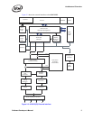
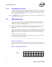
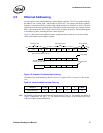
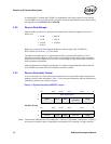
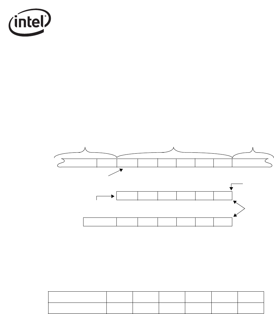
Figure 2-5 shows the bit/byte addressing order comparison between what is on the wire and the
values in the unique receive address registers.
Figure 2-5. Example of Address Byte Ordering
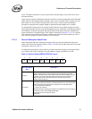
The address byte order numbering shown in Figure 2-5 maps to Table 2-2. Byte #1 is first on the
wire.
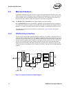
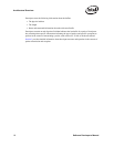
Table 2-2. Intel® Architecture Byte Ordering
Note: The notation in this manual follows the convention shown in Table 2-2. For example, the address in
Table 2-2 indicates 00_AA_00_11_22_33h, where the first byte (00h_) is the first byte on the wire,
with bit 0 of that byte transmitted first.
Preamble & SFD Destination Address Source Address
Bit 0 of this byte is first on the wire
Destination address stored
internally as shown here
dest_addr[0]
Multicast bit
...55 D5 00 11 22 33 ...XXX00 AA
33...
001122
2233 00AA0011
00AA
IA Byte # 1 (LSB) 2 3 4 5 6 (MSB)
Byte Value (Hex) 00 AA 00 11 22 33