


Software Developer’s Manual 239
Register Descriptions
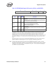
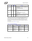
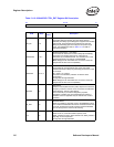
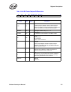
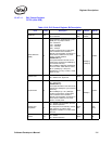
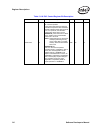
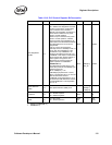
Table 13-14. MDI Control Register Bit Description
31 30 29 28 27 26 25 21 20 16 15 0
RSV E I R OP PHY REG DATA
Field Bit(s)
Initial
Value
Description
DATA 15:0 X
Data
In a Write command, software places the data bits and the
Ethernet controller shifts them out to the PHY. In a Read
command, the Ethernet controller reads these bits serially from
the PHY and software can read them from this location.
REGADD 20:16 0b PHY Register Address: Reg. 0, 1, 2, ...31
PHYADD 25:21 0b
PHY Address
The Internal PHY’s MDI address for each MAC is 0001b
OP 27:26 0b
Opcode
01b = MDI Write
10b = MDI Read
All other values are reserved.
R280b
Ready Bit
Set to 1b by the Ethernet controller at the end of the MDI
transaction (for example, indication of a Read or Write
completion). It should be reset to 0b by software at the same
time the command is written.
I290b
Interrupt Enable
When set to 1b by software, it causes an Interrupt to be
asserted to indicate the end of an MDI cycle.
E300b
Error
This bit is set to 1b by hardware when it fails to complete an
MDI read. Software should make sure this bit is clear (0b)
before issuing an MDI read or write command.
Reserved 31 0b
Reserved
Reads as 0b.