


Software Developer’s Manual 387
Diagnostics and Testability
15.2.1 EXTEST Instruction
This instruction allows testing of off-chip circuitry and board level interconnections. Data is
typically loaded onto the latched parallel outputs of the boundary-scan shift register stages using
the SAMPLE/PRELOAD instruction prior to selection of the EXTEST instruction.
15.2.2 SAMPLE/PRELOAD Instruction
This mandatory instruction allows a snapshot of the normal operation of the component to be taken
and examined. It also allows data values to be loaded onto the latched parallel outputs of the
boundary-scan shift register prior to selection of the other boundary-scan test instructions.
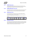
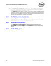
15.2.3 IDCODE Instruction
The IDCODE instruction provides information on the base component. When an Ethernet
controller identification register is included in a component design, the IDCODE instruction is
forced into the instruction register’s parallel output latches.
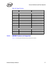
For example, the 82546EB controller’s ID is determined and derived from the manufacturer as
follows:
15.2.4 BYPASS Instruction
This instruction is the only instruction defined by the standard that causes operation of the bypass
register. The bypass register contains a single-shift register stage and is used to provide a minimum
length serial path between the TDI and TDO pins of a component when no test operation of that
component is required. This allows more rapid movement of test data to and from other
components on a board that are required to perform test operations.
Component
Product Code
Ver V Product Gen Model Manf ID 1
ID Code
(hex)
82546EB 0001 1 001001 0010 00100 00000001001 1 19244013