


240 Software Developer’s Manual
Register Descriptions
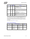
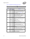
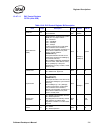
13.4.7.1 PHY Registers
This document uses a special nomenclature to define the read/write mode of individual bits in each
register. See Table 13-15.
For all binary equations appearing in the register map, the symbol “|” is equivalent to a binary OR
operation.
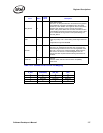
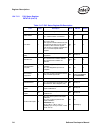
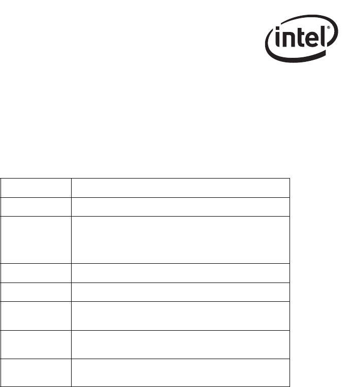
Table 13-15. PHY Register Bit Mode Definitions
Register Mode Description
LH Latched High. Event is latched and erased when read.
LL
Latched Low. Event is latched and erased when read. For
example, Link Loss is latched when the PHY Control
Register bit 2 = 0b. After read, if the link is good, the PHY
Control Register bit 2 is set to 1b.
RO Read Only.
R/W Read and Write.
SC
Self-Clear. The bit is set, automatically executed, and then
reset to normal operation.
CR
Clear after Read. For example, 1000BASE-T Status
Register bits 7:0 (Idle Error Counter).
Update
Value written to the register bit does not take effect until
software PHY reset is executed.