


132 Software Developer’s Manual
Power Management
6.3.1.3 D0a (D0 active)
Once memory space is enabled, all internal clocks are activated, the Ethernet controller enters an
active state, and can then transmit and receive packets if properly configured by the software
driver. The controller also signals the PHY (if using the internal PHY) to indicate full speed/
power
1
. If APM Wakeup was activated it remains active. The software driver can deactivate APM
Wakeup by writing to the Wakeup Control Register (WUC), or activate other Wakeup Filters by
writing to the Wakeup Registers.
6.3.1.4 D3
Prior to transition from D0 to the D3 state, the software driver must ensure the Ethernet controller
transmit and receive functions have been disabled and all pending bus transactions are complete or
cleanly terminated. If Wakeup capability is needed, the software driver needs to set up the
appropriate Wakeup registers and the system needs to write a 1b to the
PME_En bit of the Power
Management Control / Status Register (PMCSR) prior to the transition to D3.
When the system writes a 11b to the
PowerState field of the Power Management Control/Status
Register (PMCSR) the Ethernet controller transitions to D3. Any Wakeups that are enabled remain
enabled. Upon transitioning to D3 the Ethernet controller clears the Memory Access Enable or the
I/O Access Enable bit of the PCI Command Register, which disables memory access decode. In
D3, the Ethernet controller only responds to PCI configuration accesses. It won’t generate master
cycles, transmit any frames on the TBI/internal SerDes
2
/internal PHY interface, or transmit idles in
TBI mode/internal SerDes if Wakeup is enabled.
For power savings the Ethernet controller shuts down some internal clocks and registers.
To transition back to D0u, the system writes a 00b to the
Power State field of the Power
Management Control/Status Register (PMCSR).
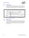
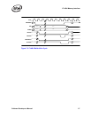
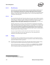
6.3.2 Timing
The following sections give detailed timing for the state transitions. In the diagrams the dotted
connecting lines represent the Ethernet controller’s requirements, while the solid connecting lines
represent the Ethernet controller’s guarantees.
Note: The following timing diagrams are not to scale. The clocks edges are shown to indicate running
clocks only and are not used to indicate the actual number of cycles for any operation.
If CLK_RUN# functionality is enabled in the EEPROM, then the
82541PI/GI/EI and 82540EP
Ethernet controllers assert the CLK_RUN# pin when it requires the PCI clock. Otherwise, the
clock is not required and the system might shut the PCI clock off.
1. Not applicable to the 82541xx or 82547GI/EI.
2. Not applicable to the 82541xx, 82547GI/EI, or 82540EP/EM.