


Software Developer’s Manual 231
Register Descriptions
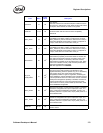
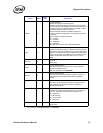
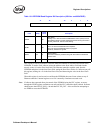
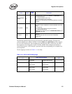
Table 13-8. EEPROM Read Register Bit Description (82541xx and 82547GI/EI)
This register is used by software to cause the Ethernet controller to read individual words in the
EEPROM. To read a word, software writes the address to the
Read Address field and simulta-
neously writes a 1b to the
Start Read field. The Ethernet controller reads the word from the
EEPROM and places it in the
Read Data field, setting the Read Done filed to 1b. Software can poll
this register, looking for a 1b in the
Read Done filed, and then using the value in the Read Data
field.
When this register is used to read a word from the EEPROM, that word is not written to any of
Ethernet controller’s internal registers even if it is normally a hardware accessed word.
Note: If software has requested direct pin control of the EEPROM using the EEC register, an access
through the EERD register mechanism can stall until the EEC control has been released. Software
should ensure that EEC.EE_REQ = 0b and that EEC.EE_GNT = 0b as well before attempting to
use EERD to access the EEPROM.
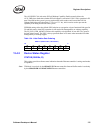
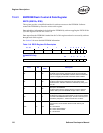
31 16 15 2 1 0
Data Address DONE START
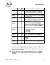
Field Bit(s)
Initial
Value
Description
START 0 0b
Start Read
Writing a 1b to this bit causes the EEPROM to read a (16-bit) word at
the address stored in the EE_ADDR field and then storing the result in
the EE_DATA field. This bit is self-clearing.
DONE 1 0b
Read Done
Set to 1b when the EEPROM read completes.
Set to 0b when the EEPROM read is in progress.
Writes by software are ignored.
ADDR 15:2 X
Read Address
This field is written by software along with Start Read to indicate the
word to read.
DATA 31:16 X Read Data. Data returned from the EEPROM read.