


130 Software Developer’s Manual
Power Management
6.3 D3
cold
support
If the AUX pin is connected to logic 1b, the Ethernet controller advertises D3
cold
Wakeup support.
The amount of power required for this function (which includes the entire Ethernet port circuitry)
is advertised in the Power Management Data Register which is loaded from the EEPROM.
If D3
cold
is supported, the PME_En and PME_Status bits of the Power Management Control/Status
Register (PMCSR), as well as their shadow bits in the Wakeup Control Register (WUC) are not
reset by RST#. If D3
cold
Wakeup is not supported, PMCSR and WUC is reset on the deassertion
(rising edge) of RST#.
The only effect of setting AUX to 1b is advertising D3
cold
Wakeup support and changing the reset
function of
PME_En and PME_Status. The 82541PI/GI can enter a fully-disabled low-power state
in D3
cold
if an enable bit is set in the EEPROM. All remaining Ethernet controllers do nothing
different in D3
cold
compared to D3
hot
. AUX_POWER is level sensitive, and any changes are
immediately reflected in the D3
cold
Wakeup advertisements and the PME_En and PME_Status
reset function.
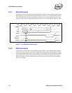
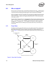
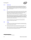
6.3.1 Power States
The Ethernet controller supports D0 and D3 power states defined in the PCI Power Management
Specification. D0 is divided into two sub-states: D0u, and D0a. In addition, it supports a Dr state
that is entered when RST# is asserted. Dr behaves the same as D3 except that the PCI bus is
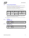
isolated. Figure 6-1 illustrates the power states and the conditions that cause transitions from state
to state.
Figure 6-1. Power State Transitions
Dr* D0u
D3 D0a
RST# assertion
RST#
deassertion
RST#
assertion
Write 11b to
Power State
Enable Memory
Access
*equivalent to D3 except PCI pins are floated
LAN_POWER_GOOD
assertion
RST#
assertion
Write 00b
to Power
State