


98 Software Developer’s Manual
EEPROM Interface
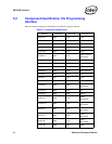
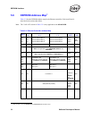
5.6 EEPROM Address Map
1
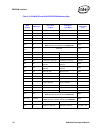
Table 5-2 lists the EEPROM address map for the Ethernet controllers. Each word listed is
described in the sections that follow.
Note: The “LAN A/B” column in Table 5-2 is only applicable to the 82546GB/EB.
1. Refer to Table 5-3 for the 82544GC/EI and 82541ER EEPROM address map.
Table 5-2. Ethernet Controller Address Map
Word
Used
By
Bit
15 - 8
Bit
7 - 0
Image
Value
LAN
A/B
00h
01h
02h
HW
HW
HW
Ethernet Address Byte 2
Ethernet Address Byte 4
Ethernet Address Byte 6
a
Ethernet Address Byte 1
Ethernet Address Byte 3
Ethernet Address Byte 5
IA(2,1)
IA(4,3)
IA(6,5)
LAN
A/B
(both)
03h Compatibility High Compatibility Low 0000h both
04h SW
SerDes Configuration
Note: Not applicable to the 82540EP/EM, 82541xx, and
82547GI/EI
FFFFh both
05h SW
EEPROM Image Version
Note: Applicable to the 82541xx and 82547GI/EI only
0000h N/A
05h
06h
07h
Compatibility High
(Words 06h and 07h reserved
for the 82541xx and 82547GI/
EI)
Compatibility Low
(Words 06h and 07h reserved
for the 82541xx and 82547GI/
EI)
0000h
0000h
0000h
both
08h
09h
PBA, byte 1
PBA, byte 3
PBA, byte 2
PBA, byte 4
0Ah HW Init Control 1
4408h
640Ah for
the
82541xx
and
82547GI/EI
both
0Bh HW Subsystem ID (Vendor)
see Table
5-1 for
specific
image
values
both
0Ch HW Subsystem Vendor ID 8086h both