


Software Developer’s Manual 79
PCI Local Bus Interface
4.1.1 PCI-X Configuration Registers
The Ethernet controller supports additional configuration registers that are specific to PCI-X.
These registers are visible in conventional PCI and PCI-X modes, although they only affect the
operation of PCI-X mode. The PCI-X registers are linked into the Capabilities linked list.
Note: The 82540EP/EM, 82541xx, and 82547GI/EI do not support PCI-X mode.
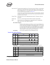
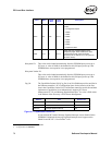
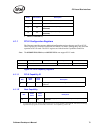
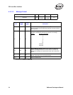
Figure 4-2. PCI-X Capability Registers
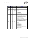
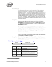
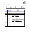
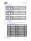
4.1.1.1 PCI-X Capability ID
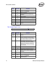
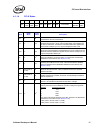
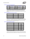
4.1.1.2 Next Capability
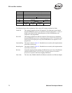
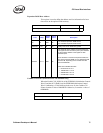
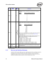
12 0b Received Target Abort.
13 0b Received Master Abort.
14 0b
Signaled System Error (not applicable to the
82547GI/EI).
15 0b
Detected Parity Error (not applicable to the
82547GI/EI).
a. 82541xx and 82547GI/EI only.
Bit(s) Initial Value Description
Byte Offset Byte 3 Byte 2 Byte 1 Byte 0
E4h PCI-X Command Next Capability PCI-X Capability ID
E8h PCI-X Status
Bits
Read/
Write
Initial
Value
Description
7:0 R 7
Capability ID - Identifies the PCI-X register set in the capabilities
linked list.
Bits
Read/
Write
Initial
Value
Description
7:0 R F0
a
a. In conventional PCI mode, Message Signaled Interrupts can also be disabled in the EEPROM. If disabled, the Message
Signaled Interrupt registers are not visible, and PCI-X’s “Next Capability” pointer is 0b.
Next Capability – points to the next capability in the capabilities
linked list.