


Software Developer’s Manual 375
General Initialization and Reset Operation
Note: IPGR1 and IPGR2 are not needed in full duplex, but are easier to always program to the values
shown.
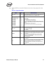
Table 14-1. Signal Descriptions
Signal Ball Name and Function
LOS / LINK A10
Loss of Signal (TBI) / Link Indication. Loss of signal (high for lost
signal) from the optical transceiver when LINK_MODE equals 11b;
active high link indication from PHY in GMII/MII mode.
TX_DATA[9] / TX_ER
TX_DATA[8] / TX_EN
TX_DATA[7]
TX_DATA[6]
TX_DATA[5]
TX_DATA[4]
TX_DATA[3]
TX_DATA[2]
TX_DATA[1]
TX_DATA[0]
C7
D7
E6
B5
E5
C5
E4
C4
D5
D4
Transmit Data.
TBI: TX_DATA[9:0] for transmit data bus.
GMII: TX_DATA[7:0] for transmit data bus.
TX_ER forces propagation of transmit errors and is used for carrier
extension. TX_EN is asserted to indicate transmission of data on the
interface.
MII: TX_DATA[3:0] for transmit data bus.
TX_ER is not used. TX_EN is used for transmit enable signal.
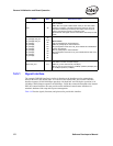
GTX_CLK C6
Transmit Clock.
TBI: 125 MHz transmit clock.
GMII: Operates at 125 MHz.
MII: Undefined.
EWRAP E10
Enable Wrap.
TBI: EWRAP is low in normal operation. When it is high, the SerDes
device is forced to transceiver loopback the serialized transmit data
to the receiver.
This pin is tri-stated during EEPROM read. In order to avoid a
floating input in an external SerDes, a weak external pull-down
should be connected to this pin.
GMII / MII: Not used.
COL E7
Collision.
TBI: Undefined.
GMII / MII: This signal indicates that a collision was detected on the
medium by the PHY. This signal remains asserted while the collision
persists. For half-duplex transceivers, this signal indicates
simultaneous transmission and reception. This signal is ignored in
full-duplex mode.
Normal Mode: This signal must be connected to VSS except for test
mode.